


6
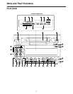
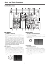
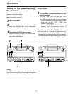
Front panel
1
POWER switch
When this switch is pressed, the power is turned on
and the counter display area lights; when it is
pressed again, the power is turned off.
2
Cassette insertion slot
Newsgathering cassettes and general-purpose
cassettes are inserted into this slot.
<Note>
Do not insert DV cassettes, which are designed for
general consumer applications.
3
EJECT button
When this button is pressed, the tape inside is
unloaded and several seconds later it is
automatically ejected.
If the counter display area is set to the CTL display,
the display will be reset.
4
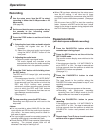
REC and REC INH lamps
REC:
This lamps lights during recording.
REC INH:
This lamp lights when the cassette is set
to the accidental erasure prevention
status. It also lights when the REC
INHIBIT switch
P
is at the ON setting.
In this status, recording is not possible.
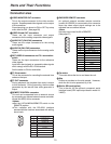
5
REMOTE lamp
This lamp lights when the REMOTE setting has
been selected by the LOCAL/MENU/REMOTE
switch
=
.
6
WIDE lamp
This lamp lights when the WIDE mode has been
selected.
7
SCH lamp
This lamp lights when the external sync signal
subcarrier phase is within the specified range.
8
SERVO lamp
This lamp lights when the drum servo and capstan
servo lock.
9
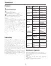
Channel condition lamps
One of these lamps lights in accordance with the
error rate statuses. (Green
Blue Red)
Green:
This lamp lights when both the error rates for
the video and audio playback signals are at
an acceptable level.
Blue:
This lamp lights when the error rate for
either the video and audio playback signals
has deteriorated. A normal playback picture
will appear even when this lamp is lighted.
Red:
This lamp lights when either the video or
audio playback signals are subject to
correction or interpolation.
:
Level meter
This displays the levels of the audio signals.
The level of the input audio signals is displayed
during recording and E-E selection; the level of the
output audio signals is displayed during playback.
;
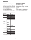
Cassette insertion and tape travel display lamp
This lamp lights when a cassette has been inserted
into the unit.
: When a tape has been inserted and the
STANDBY ON status has been
established
: When a tape has been inserted and the
STANDBY OFF (HALF LOADING) status
has been established
: While the tape is traveling, the segment
display moves as the tape travels.
: The “” symbol at the stopped side
flashes when the fan has shut down.
<
Counter display area
The TC and CTL counts, the on-screen information
and other messages are displayed in this area.
If DC power is supplied to the unit, the whole
display will flash as a warning when the voltage has
dropped.
When the voltage drops to 10.6V or so, the power
will automatically be turned off.
=
LOCAL/MENU/REMOTE switch
This switch is set when menu settings are to be
performed or when the unit is to be controlled from
an external source.
LOCAL:
Set here when the unit is to be controlled
using the controls on its operation panel.
MENU:
Set here when on-screen menu settings
are to be performed.
REMOTE:
Set here when the unit is to be controlled
using an external remote controller
(model AJ-A95P).
Parts and Their Functions