


11
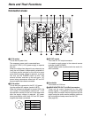
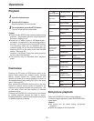
CH 1 CH 2AUDIO
OUT
CH 1 CH 2AUDIO
IN
REF VIDEO IN
VIDEO
IN OUT
ON
OFF
75 Ω
TC IN
TC OUT
VIDEO MON
OUT
AUDIO
MON OUT
LR
ENCODER
REMOTE
DC OUT
12V 250mA
AC IN
REMOTE
DC IN
SIGNAL
GND
FUSE 125V 2.5A
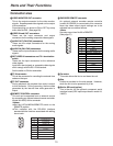
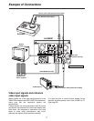
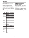
Example of Connections
Monitor
Speakers with
built-in amplifier
VIDEO MONITOR output
VIDEO MONITOR output
AC cable
(packed with unit)
AC 120V or AC adaptor
AJ-B75 (option)
4-pin DC power cable (packed with AJ-B75)
9-pin RS-422A cable (option)
4-pin DC power cable (packed with AJ-A95P)
AJ-D95DC
AJ-A95P
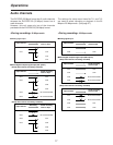
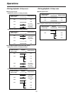
Video input signals and reference
video input signals
When signals are to be input simultaneously to the
VIDEO IN connectors and REF VIDEO IN connectors,
make sure that the respective signals are
synchronized.
If these signals are not synchronized, the E-E picture
may dance, the advance of the time code display may
slow down, the response to operations may slow
down or some other phenomenon may occur
(although the signals will be recorded normally).
In a case like this, a normal picture display can be
restored by setting setup menu item No.600 to VF.
(See page 35)