


9
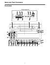
CH 1 CH 2AUDIO
OUT
CH 1 CH 2AUDIO
IN
REF VIDEO IN
VIDEO
IN OUT
ON
OFF
75 Ω
TC IN
TC OUT
VIDEO MON
OUT
AUDIO
MON OUT
LR
ENCODER
REMOTE
DC OUT
12V 250mA
AC IN
REMOTE
DC IN
SIGNAL
GND
FUSE 125V 2.5A
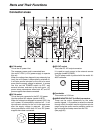
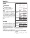
Connector areas
Parts and Their Functions
3
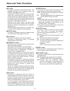
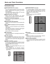
DC OUT socket
This is the DC 12V output connector.
It is used to supply power to the external remote
controller (model AJ-A95P).
The DC power cable is packed with the model AJ-
A95P controller.
4
Fuse holder
This contains a 2.5A fuse.
5
AUDIO MONITOR OUT (Lch/Rch) connectors
These are the output connectors for the audio
monitor signals. It is possible to select the channel
through which the audio monitor signals are to be
output using the audio monitor selector switch on
the front panel and setup menu item No.708.
(See page 36)
3
1
2
4
Pin No. Signal
1 Ground
2
3
4 +12 V
1
2
3
4
Pin No. Signal
1 Ground
2
3
4 +12 V
1
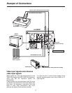
AC IN socket
This is the AC power inlet.
The accessory power cord is connected here.
Use an AC 120V (±10%) power supply to operate
this unit.
When the voltage has dropped to an extremely low
level, the unit’s power is automatically switched off.
It will take several minutes for the unit to be reset
even after the supply voltage is restored. In a case
like this, set the POWER switch to OFF, wait
several minutes, and start up the unit again. AC
power takes precedence when both AC and DC
power supplies have been connected.
2
DC IN socket
This is the input connector for the DC 12V power.
Use the optional AC adaptor (model AJ-B75).
When the voltage has dropped to around 10.6V, the
unit’s power is automatically switched off. It will
take several minutes for the unit to be reset even
after the supply voltage is restored. AC power
takes precedence when both AC and DC power
supplies have been connected.