


10
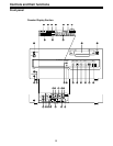
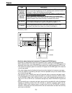
Controls and their functions
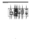
#2 DIAG button
When this is pressed, VTR information is displayed. When it is pressed again, the original
display is restored.
There are two types of VTR information: “HOURS METER” information and “WARNING”
information. Switching between these types is enabled by pressing the cursor buttons
( , ).
Indicated on the “HOUR METER” screen are the power-on time, drum rotation time, tape
travel time, loading count, etc.
Indicated on the “WARNING” screen are the warnings.
• The status information on the IEEE1394 interface can be referenced when the
AJ-YAD455P digital video interface board is used.
#3 VIDEO INPUT switch
This switches the video input signal.
DVCPRO/DV: Set to this position when recording digital video interface signals (IEEE1394).
(At the same time, audio input signals from IEEE1394 will also be
recorded.)*
1
SDI: For selecting serial component digital video signal (SMPTE 259M-C)
recording.*
2
ANALOG: For selecting analog video signal recording.
Select the analog video signal as follows to correspond with the input
signal.
Y PB PR: For recording an analog component video signal.
CMPST: For recording an analog composite video signal.
S-VIDEO: For recording a S-VIDEO signal.
*1: The AJ-YAD455P digital video interface board (optional accessory) is required for this.
*2: The AJ-YA455P serial interface board (optional accessory) is necessary.
#4 AUDIO INPUT switch
This switches the audio input signal.
SDI: For selecting serial digital audio signal (SMPTE 272M-A) recording.*
AES/EBU: For recording a digital audio signal.
ANALOG: For recording an analog audio signal.
* The AJ-YA455P serial interface board (optional accessory) is required for this.
<Notes>
• The DVCPRO/DV format will also apply to the audio input signals when DVCPRO/DV
has been selected by the VIDEO INPUT switch #3.
• When SD or AES/EBU is to be selected, the reference video signal must be input, and
the audio data synchronized with the REF VIDEO signal must be supplied.
#5 REMOTE/LOCAL switch
This is set to control the unit from an external component using the REMOTE, RS-232C or
digital video interface (IEEE1394) connector.
REMOTE: Set here to control the unit by a component connected to the unit using the
9-pin REMOTE, RS-232C or digital video interface (IEEE1394) connector.
LOCAL: Set here to control the unit using the switches and controls on the unit’s control
panel.