


24 C2629M-A (6/07)
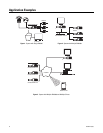
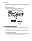
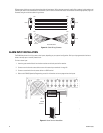
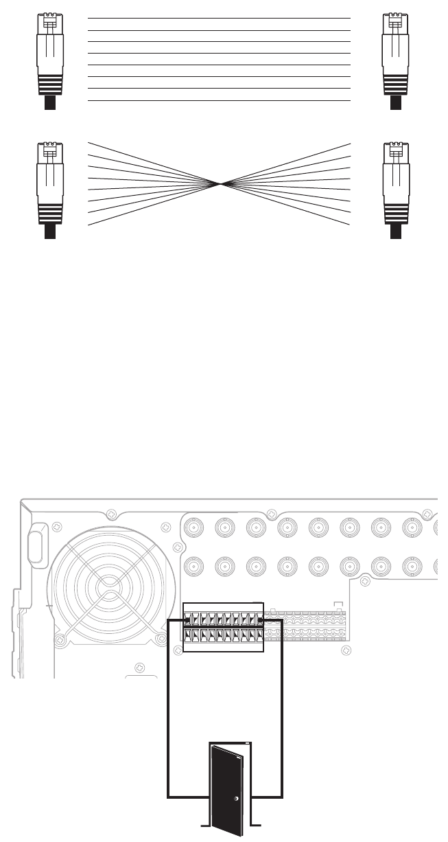
Different types of devices may require alternative cable wiring schemes. Wiring schemes commonly used by Pelco products include straight and
rollover types. Refer to the documentation included with your PTZ device to ensure that cables and connectors are wired appropriately.
Figure 13
illustrates straight and rollover cable wiring schemes.
PIN
1
2
3
4
5
6
7
8
PIN
1
2
3
4
5
6
7
8
PIN
1
2
3
4
5
6
7
8
PIN
1
2
3
4
5
6
7
8
RJ-45
STRAIGHT CABLE
ROLLOVER CABLE
RJ-45
RJ-45 RJ-45
Figure 13. Cable Wiring Schemes
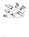
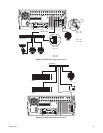
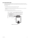
ALARM INPUT INSTALLATION
The DX8100 has either 8 or 16 dry contact alarm inputs, depending on your system’s configuration. Each input is programmed to function as
either a normally open or normally closed circuit.
To wire an alarm input:
1. Insert the green terminal blocks into the alarm sockets on the back panel of the recorder.
2. Connect one wire from the source device to one of the sensor input terminals 1 through 16.
3. Connect a second wire from the source device to a GND terminal.
4. Refer to the DX8100 Operation/Programming manual for information on how to program the alarm inputs.
IN1 IN2 IN3 IN4 IN5 IN6 IN7 IN8 IN9
IN9 IN10 IN11 IN12 IN13 IN14 IN15 IN16
OUT16OUT15OUT14OUT13OUT12OUT11OUT10
OUT
9OUT9
OUT8OUT7OUT6OUT5OUT4OUT3OUT2OUT1
ALARMINPUTS RELAYOUTPUTS
12245678GND
9 10111213141516
12245678GND
9 101112131415169 10111213141516
CRT
ALARM
OUTPUT 1
GND
Figure 14. Alarm Terminal Installation