C2629M-A (6/07) 75
Appendix F: Connecting a KBD300A Keyboard
This section describes how to connect the KBD300A keyboard to the DX8100 DVR. The KBD300A allows you to control DX8100 display and
camera functions. For example, you can select cameras from the site tree, select view panes and divisions, zoom in and out, and control PTZ
operation from the KBD300A keyboard rather than a mouse.
Installation of the KBD300A is accomplished in two steps:
• Hardware installation, which is described in this section.
• Software configuration, which is described in the DX8100 Operations and Programming Manual.
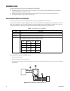
The DX8100 supports the RS-422 data communications protocol to implement the interface with the KBD300A. For more information about
setting up KBD300A RS-422 communications settings, refer to Operation and Programming Manual.
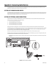
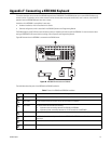
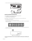
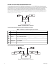
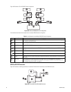
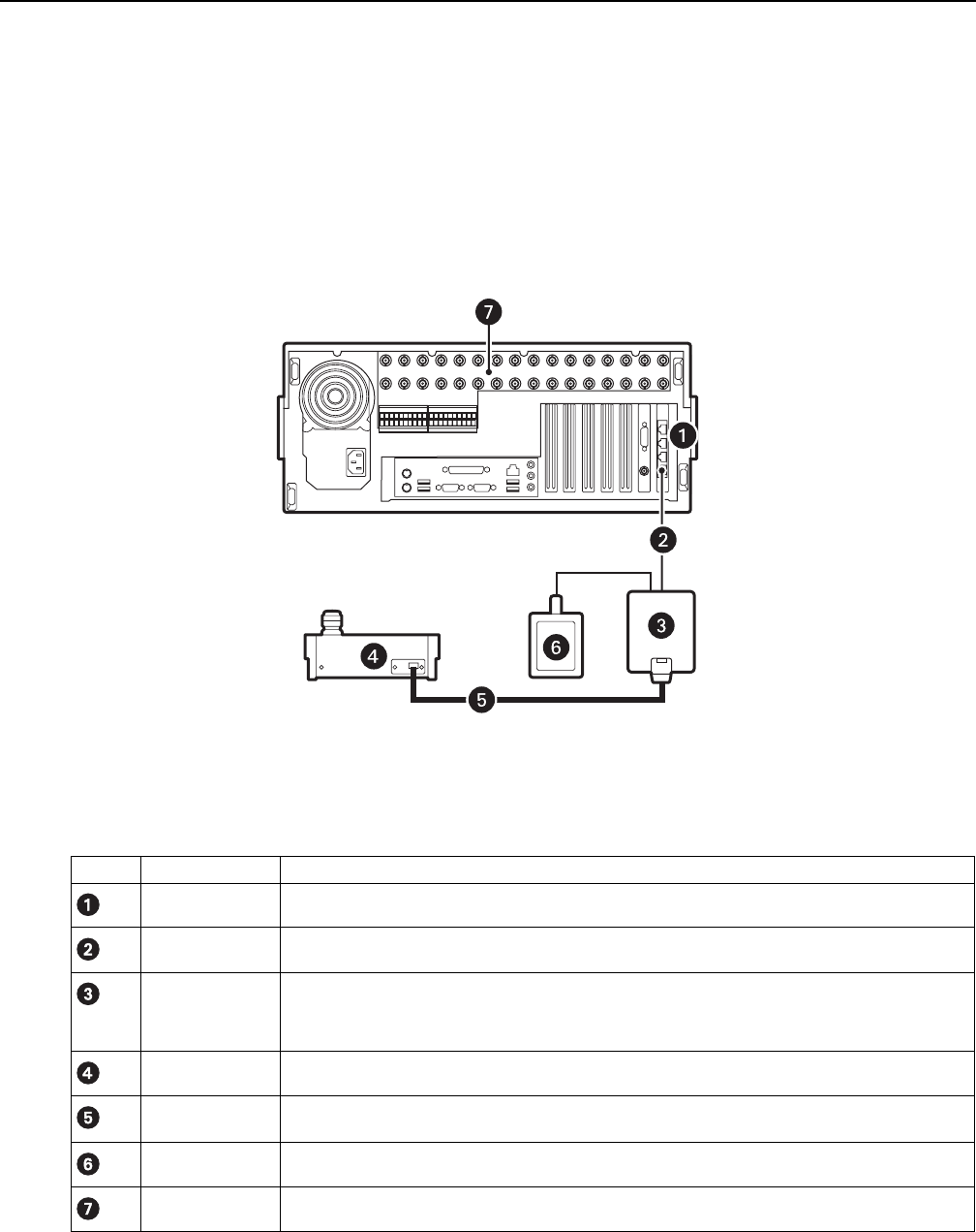
Figure 99 illustrates how the KBD300A is connected to the DX8100 server.
Figure 98. KBD300A Connected to the DX8100
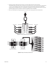
The table below describes parts of the KBD300A and DX8100 installation.
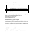
Table F. Parts of the DX8100 and KBD300A Installation
Item Part Description
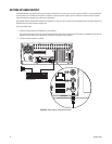
RJ-45 The DX8100 provides four RJ-45 ports identified as Port 1–Port 4, with Port 1 being on the bottom.
Data cable A user-supplied cable that connects the RJ-45 wall block to the DX8100.
Wall block A surface mount box that does the following:
• Implements data connectivity between the DX8100 and KBD300A.
• Implements power connectivity between the 12 VAC transformer and KBD300A.
Keyboard.
A 25-foot keyboard data and power cable for the KBD300A. The KBD300A uses this cable to connect to the
wall block.
A 12 VAC transformer that powers the KBD300A.
DX8100 server.
KBD300A
Keyboard data cable
Wall transformer
DX8100


