


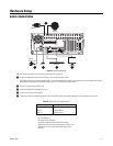
C2629M-A (6/07) 25
RELAY OUTPUT INSTALLATION
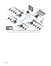
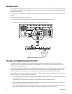
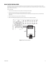
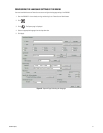
The DX8100 has either 8 or 16 relay outputs, depending on your system’s configuration. Each output is programmed to function as either a
normally open or normally closed circuit. A signal from a relay output will operate the device connected to the output. The maximum relay power
rating is 120 VAC, 0.5 A; 24 VDC, 1 A.
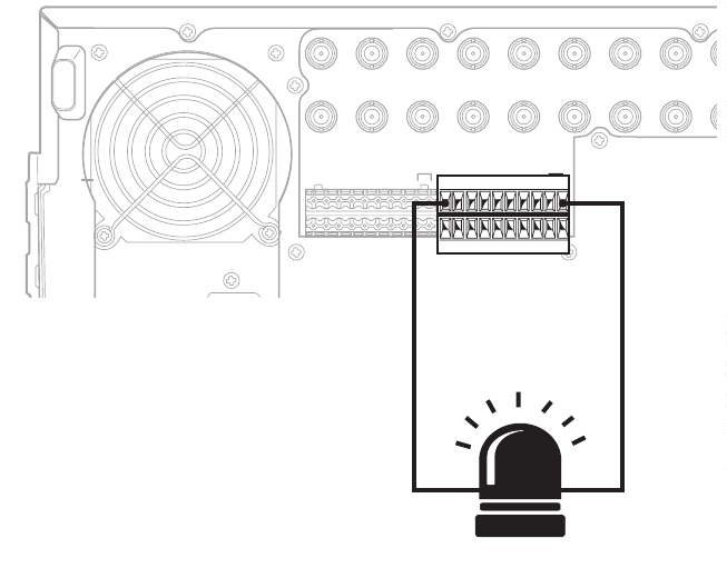
To wire a relay output:
1. Insert the blue terminal blocks into the relay sockets on the back panel of the recorder.
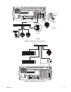
2. Connect one wire from the device to one of the relay output terminals 1 through 16.
Relay outputs do not have to correspond numerically to alarm inputs. All sensor input and relay output actions can be linked through
programming.
3. Connect a second wire from the relay device to a GND terminal.
4. Refer to the DX8100 Operation/Programming manual for information on how to program relay outputs.
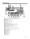
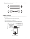
IN1 IN2 IN3 IN4 IN5 IN6 IN7 IN8 I
NIN9 IN10 IN11 IN12 IN13 IN14 IN15 IN16
OUT16OUT15OUT14OUT13OUT12OUT11OUT10
O
UOUT9
OUT8OUT7OUT6OUT5OUT4OUT3OUT2OUT1
ALARMINPUTS RELAYOUTPUTS
12245678GND
9 10111213141516
12245678GND
9 10111213141516
9 10111213141516
CRT
RELAY
OUTPUT 1
GND
Figure 15. Relay Terminal Installation