82 C2629M-A (6/07)
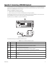
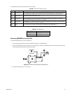
Figure 106 illustrates a RS-422 ATM/POS device configuration.
ᕥ
ᕡ
ᕧᕧ
ᕣ
ᕣ
ᕦᕦ
ᕤ ᕤ
ᕡ
ᕢ ᕢ
ᕨ ᕨ
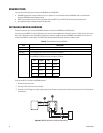
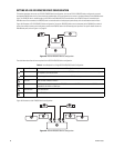
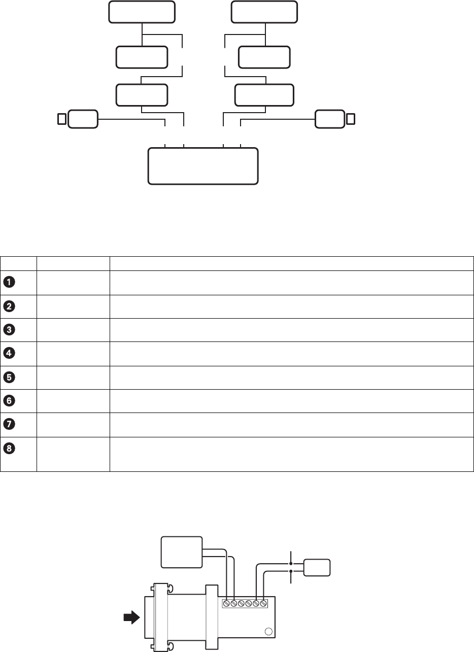
Figure 105. Multiple ATM/POS Device Configuration
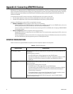
The table below describes the items required for the multiple ATM/POS device configuration.
Table L. Items Required for the Multiple ATM/POS Device Configuration
Item Part Description
Camera The designated cameras positioned to monitor the ATM/POS event. One or more cameras can be configured
to respond to an ATM/POS event.
Video cable A user-supplied cables that connects the cameras to the DX8100 video input.
VSI-PRO AVE VSI-PRO ATM/POS interface.
AVE triport cable used to connect the ATM/POS device to the VSI-PRO and to connect the VSI-PRO to the
PV140.
The DX8100 DVR.
The ATM/POS device.
A RS-232 to RS-422 converter that provides a bidirectional electrical interface between RS-232 and RS-422
data ports.
User-supplied RJ-45 cable that connects the PV140 to Port 1 to 4 of the DX8100 DVR. The cable is
constructed with a two-wire pigtail on one end and an RJ-45 plug on the other. For information about the
RJ-45 plug wiring, refer to
Figure 11 on page 23.
PV140-to-RS-422 Connection
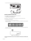
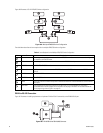
Figure 107 illustrates the cabling requirements to implement PV140-to-RS-422 connectivity to the DX8100 RJ-45 port.
ᕢ
ᕦ
ᕡ
ᕣ
ᕤ
ᕥ
Figure 106. PV140 RS-232 to RS-422/485 Converter
Triport cable
DX8100 server
ATM/POS device
PV140
Data cable


