C2629M-A (6/07) 81
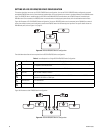
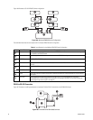
The table below describes the items required for the RS-422 ATM/POS device configuration.
Table K. Items Required for a Dual RS-422 ATM/POS Device Configuration
Item Part Description
Camera The designated cameras positioned to monitor the ATM/POS event. One or more cameras can be configured
to respond to an ATM/POS event.
Video cable A user-supplied video cables that connect the cameras to the DX8100 video input.
AVE triport cable used to connect the ATM/POS device to the VSI-PRO and to connect the VSI-PRO to the
DX8100 RS-232 COM1 or COM2 port.
VSI-PRO AVE VSI-PRO ATM/POS interface.
The ATM/POS device.
The DX8100 DVR.
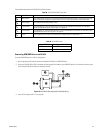
To connect the ATM/POS device and VSI-PRO in a RS-232 ATM/POS configuration:
1. Use the appropriate AVE cable to connect the VSI-PRO to the ATM/POS device. For information about connecting the VSI-PRO and ATM/
POS device, refer to the ATM/POS installation and VSI-PRO VSI-PRO Version 12.00 Operation Manual.
2. Connect the AVE RS-232 cable to the DX8100 COM1 or COM2 port.
3. Connect the VSI-PRO power transformer into the VSI-PRO.
4. Plug the VSI-PRO power transformer into an appropriate AC power source.
SETTING UP A RS-422 ATM/POS DEVICE CONFIGURATION
This section describes how to set up a RS-422 ATM/POS device configuration. This configuration is applicable for applications that have one to
four ATM/POS devices. You use the RS-422 ATM/POS device configuration to record searchable ATM/POS data that is synchronized to recorded
transaction video. You can configure multiple cameras to be associated with a transaction event.
In this configuration, the camera is connected directly to the DX8100 camera input. The ATM/POS data from each ATM/POS device is routed
through its respective VSI-PRO to a DX8100 RS-422 port. ATM/POS output is recorded by the DX8100 as data. Once recorded, the ATM/POS data
is searchable and can be displayed synchronous with the transaction video.
Interface connection for this configuration is summarized as follows:
1. Each respective camera is connected directly to the DX8100 camera input.
2. Each ATM/POS device is connected as follows:
a. Each ATM/POS device is connected to a separate VSI-PRO.
b. Each VSI-PRO device is connected to a PV140 RS-232/422 converter.
c. Each PV140 is connected to a DX8100 RS-422 port through a user-provided RJ-45 cable.
ATM/POS output is recorded by the DX8100 as data. Once recorded, the ATM/POS data is searchable and can be displayed synchronous with the
transaction video.
Data cable
ATM/POS device
DX8100 server


