


GB
1-6
GB
1-5
DIGITAL VIDEO RECORDER
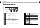
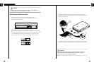
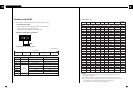
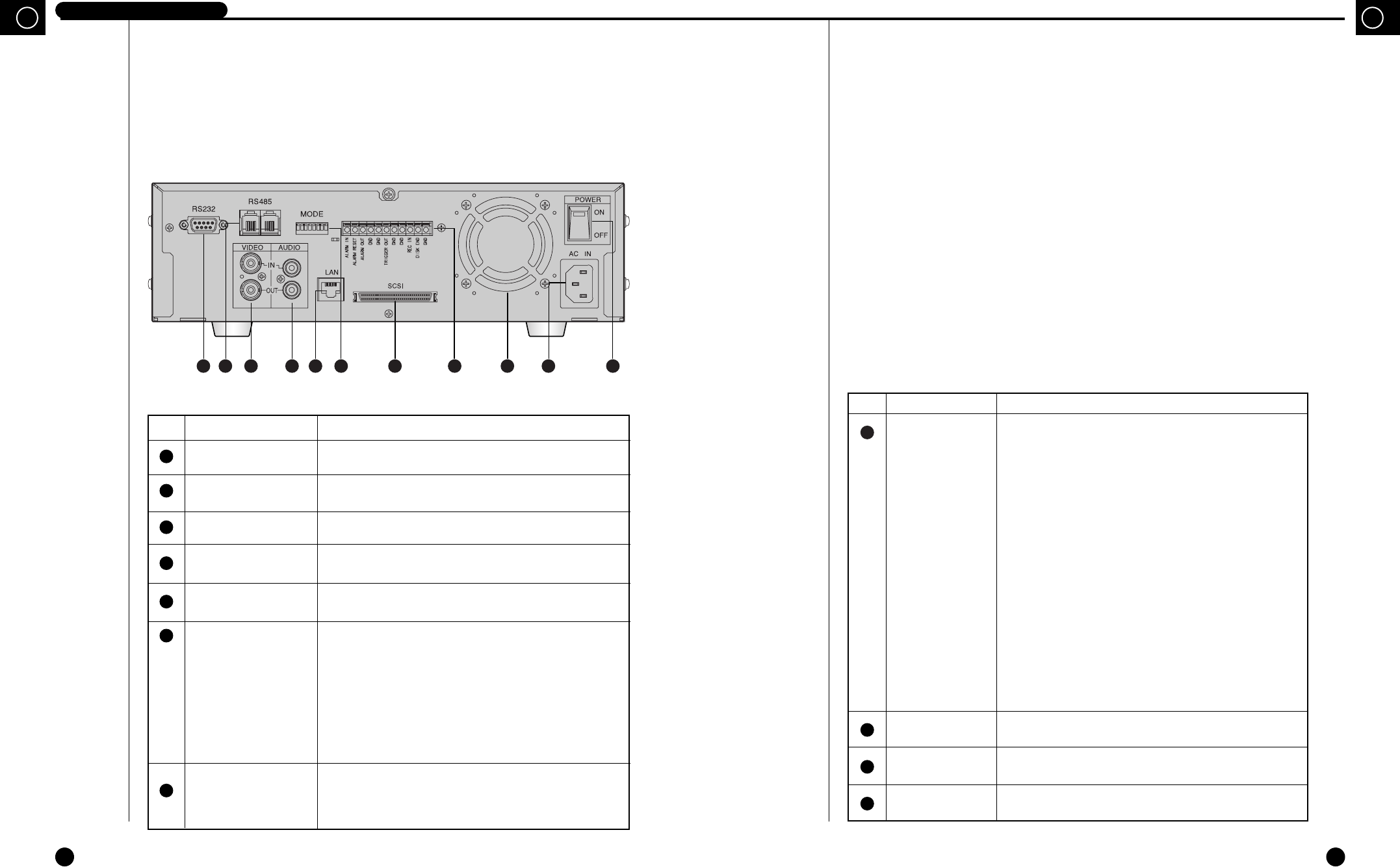
Rear View
1
2
3
4
5
No Name Function
EXTERNAL I/O
PORT
FAN
AC IN
POWER
●
ALARM IN: In the N.C. (Normally Closed) mode, the system
recognizes an alarm when a High (5V) signal is input for over
0.5 seconds. In the N.O. (Normally Open) mode, the system
recognizes an alarm when a Low (0V) signal is input for over
0.5 seconds. (Please refer to “➁ALARM DETECT TYPE”
on p. 3-18.)
●
ALARM RESET: The alarm mode is cleared when a Low (0V)
signal is input for over 0.5 seconds.
●
ALARM OUT: A High (5V) signal is output during alarm
recording.
●
TRIGGER OUT: This signal is for switching the recording
output screen of the Multiplexer.
●
REC IN: The system begins recording when a Low (0V) signal
is input for over 0.5 seconds.
●
DISK END: If the DISK END MODE of the RECORD
MODE SETUP is set to STOP, a Low (0V) signal is output for
about 1 second when the HDD becomes full during recording.
(Please refer to “➃ DISK END MODE” on p. 3-16.)
Fan
Connects power cable.
Power On/Off button.
8
9
10
11
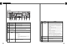
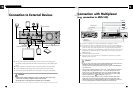
1 2 3 4 7 95 108 116
No Name Function
RS232 PORT
RS485 PORT
VIDEO IN/OUT
AUDIO IN/OUT
LAN
MODE
SCSI
Serial Port for remote control.
Serial Port for remote control.
Composite image signal I/O terminal (BNC Style Connector).
Audio Signal Input/Output Jacks (RCA Jacks).
LAN Cable Connection Terminal.
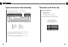
It is the DIP switch to set System ID, Direct Communication,
Termination, etc.
●
1~5 : System ID.
●
6 : Not Use.
●
7 : Termination On/Off (Of all the directly connected
systems, it sets the last system as On).
●
8 : Not Use.
SCSI Connector for Data Backup
6
7