Fibre Channel Interface Manual, Rev. D 105
10.3.2 8067 ESI interface pinouts
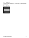
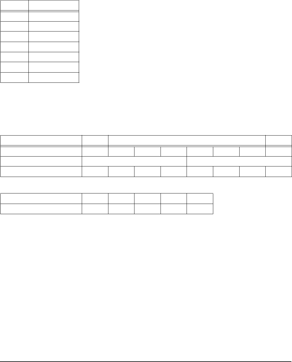
In 8067, the ESI function becomes a bi-directional interface. Three pins are defined for control functions and
the remaining four pins become a 4-bit nibble interface. Table 58 is a mapping of the Select pins to the 8067
ESI interface function. 8067 specifies that open-collector type drivers be used for signals on the P_ESI and
Select lines.
10.3.3 8067 information format
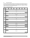
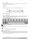
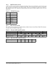
ESI in 8067 mode is transferred on the ESI interface a nibble (4 bits) at a time. Refer to Table 59 for the trans-
fer order in bits and Table 60 for byte order.
Table 58: SFF 8067 ESI pinouts
Pin ESI function
SEL 6
–DSK_WR
SEL 5
–DSK_RD
SEL 4
–ENCL_ACK
SEL 3
Data (3)
SEL 2
Data (2)
SEL 1
Data (1)
SEL 0
Data (0)
Table 59: Bit order in 8067 mode ESI transfers
MSB LSB
Bit order byte
76543210
Transfer order on ESI interface
First Nibble Second Nibble
Bit order is ESI data
D(3) D(2) D(1) D(0) D(3) D(2) D(1) D(0)
Table 60: Byte order in 8067 mode ESI transfers
Byte order in SCSI transfer
0 1 .......... n – 1 n
Byte order is ESI transfer
first second .......... n – 1 n


