278 Fibre Channel Interface Manual, Rev. D
Defect List Format
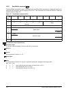
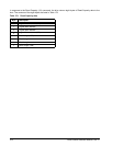
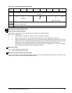
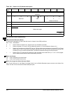
Bits 2, 1, 0 in the CDB should be 1 0 0, respectively, to signify a defect list in the Bytes from Index format, or 1 0 1, respec-
tively, to signify a defect list in the Physical Sector format. If neither of these two, the disc drive responds with the defect list
in the drive’s default format (physical sector) and creates the Check Condition status with Recovered Error sense key (1h)
and additional sense error code (1C) at the end of the Read Defect Data transfer.
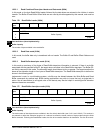
This command is intended to be used only with the Format Unit command (Section 12.5). The initiator should
not interpret or act upon this list except to resend this list as defect data in a Format Unit command. It is not
possible to relate actual physical locations to logical block addresses that are given in connection with other
commands.
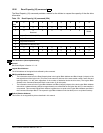
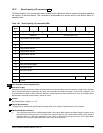
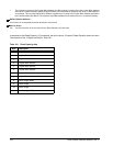
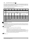
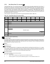
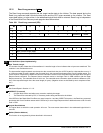
The format Defect Data header and Defect Data Descriptor bytes returned are shown in Table 183.
The first four bytes returned are the Defect List header. The P bit, G bit, and Defect List Format fields indicate
the defect format actually returned by the disc drive. The definitions are the same as for byte 2 of the Read
Defect Data Command Descriptor Block (Table 182).
The Defect List Length specifies the total length (in bytes) of all the defect descriptors available from the disc
drive. If the Allocation Length of the CDB is too small to transfer all of the defect descriptors, the Defect List
Length is not adjusted to reflect the truncation. The drive does not create the Check Condition status. The
Defect Descriptors are not required to be in ascending order.
182


