Fibre Channel Interface Manual, Rev. D 165
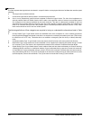
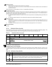
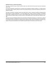
Immed (Immediate)
0 Status will be returned after the first operation has completed.
1 The target will return status as soon as the command descriptor block has been validated, and the entire defect list
has been transferred.
Check individual drive’s Product Manual, Volume 1, for applicability of this feature.
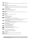
IP (Initialization Pattern)
This field indicates the type of pattern the target uses to initialize each logical block within the initiator accessible portion of
the medium (Table 100). All bytes within a logical block are written with the initialization pattern. The initialization pattern is
modified by the IP modifier field as described in Table 100.
1 An initialization pattern descriptor is included in the Format Unit parameter list immediately following the Defect List
header.
0 An initialization pattern descriptor is not included and the target uses its default initialization pattern.
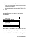
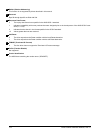
STPF (Stop Format)
1 Formatting is terminated with a Check Condition status if an error is encountered while accessing either the P or G
defect list. The sense key is set to Medium Error and the additional sense code is set to either Defect List Not Found
or Defect List Error.
0 Formatting is not terminated if an error is encountered while accessing either the P or G defect list.
VS (Vendor Specific)
Not used.
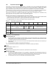
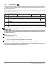
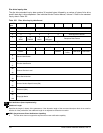
12.5.1.2 Initialization Pattern descriptor
The initialization pattern option specifies that the logical blocks contain the specified initialization pattern. The
initialization pattern descriptor is sent to the target as part of the Format Unit parameter list.
Field definitions (listed alphabetically)
Initialization Pattern (IP) and IP Modifier
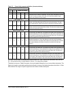
The Initialization Pattern field is modified in accordance with the specification of the IP Modifier field given in Table 100. The
Initialization Pattern is sent by the host for the drive to write in each logical block by the Format command. Refer to the table
below.
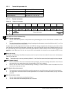
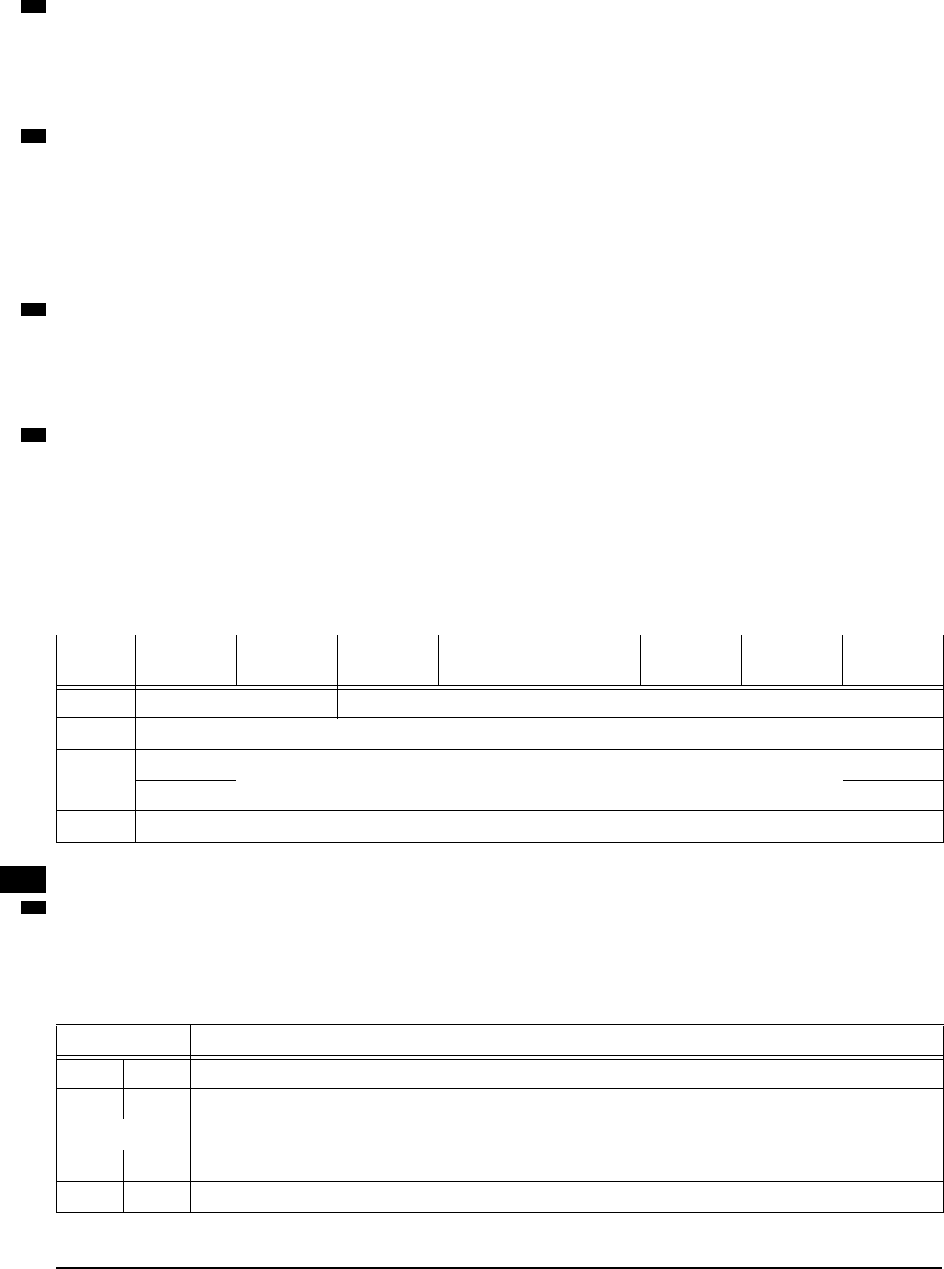
Table 99: Initialization Pattern descriptor
Bit
Byte
76543210
0
IP Modifier Reserved
1 Pattern Type
2
(MSB)
Initialization Pattern Length
3
(LSB)
0 – n Initialization Pattern
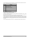
Table 100: Initialization Pattern Modifier
IP Modifier Description
00
No header. The target does not modify the initialization pattern.
01
The target overwrites the initialization pattern to write the logical block address in the first four bytes of
the logical block. The logical block address is written with the most significant byte first.
or
10
11
Reserved.
98
98
98
98
Table
number
99


