Fibre Channel Interface Manual, Rev. D 11
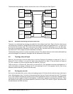
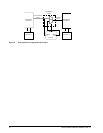
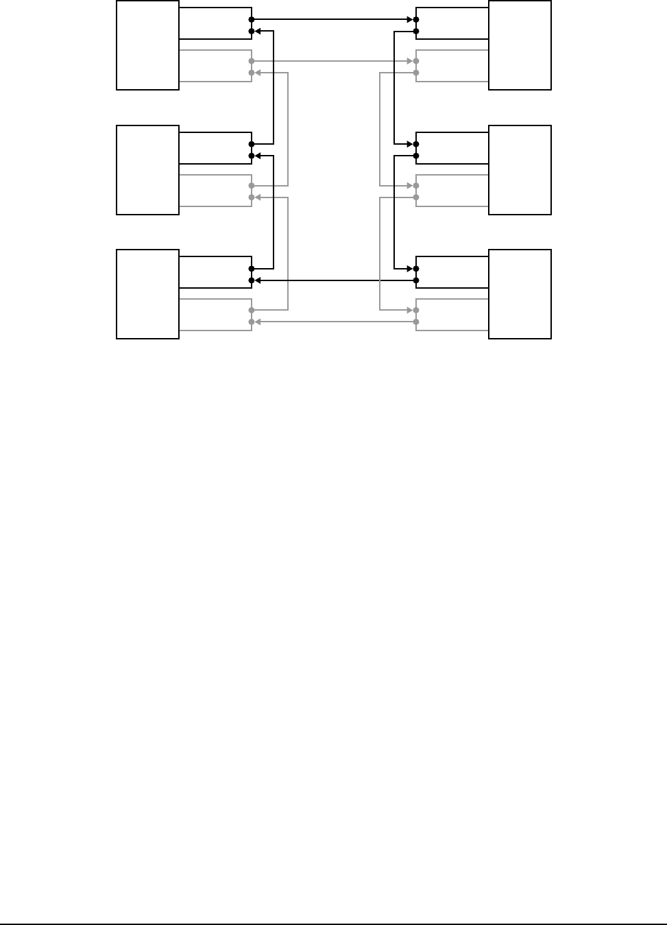
The arbitrated loop topology is used to connect from two to 126 node ports. See Figure 2.
Figure 2. Arbitrated loop topology (dual port private loop)
The ports in an arbitrated loop topology are called NL_Ports (Node Loop Ports). Each of the NL_Ports has an
input and output connection. Seagate Fibre Channel drives support dual ports (specified with a “1” in byte 6, bit
4 of the disc drive inquiry data). The actual ports are located on the host’s backpanel, not on the disc drive.
Dual ports are provided for redundancy so that if one loop fails, the other one can fulfill the loop duties. Each
drive has one FC SCA (single connector attachment) connector.
The arbitrated loop protocol is a token acquisition protocol. This means each port on the same arbitrated loop
sees all messages, but passes all messages that are addressed to other ports.
4.5 Topology and port login
Each NL_Port must sign in with the other ports on the loop. Each port first attempts to locate an FL_Port. If it
finds an FL_Port, it knows it is a part of a public loop connected to a fabric. If the port does not locate an
FL_Port, it knows it is a part of a private loop with other NL_Ports only.
There can be up to 126 active NL_Ports and up to one active FL_Port attached to the same arbitrated loop. If
an NL_Port does not attempt to discover an FL_Port and there is an FL_Port present, the NL_Port is only
allowed to access other NL_Ports on the same loop.
4.6 Port bypass circuits
So far, we’ve discussed links, ports, nodes, and topology logins. All’s fine with this model as long as the loop is
intact. What happens, then, if a device is disconnected from the loop. Doesn’t this break the loop? The answer
is no. Fibre Channel provides port bypass circuitry which bypasses the drive if it is removed, incapable of pro-
viding loop services, unable to obtain a valid address, or otherwise incapable of providing loop services. These
port bypass circuits (PBCs) are located external to the drive or other FC-AL device. Figure 3 shows the rela-
tionship between the PBC and drive.
Node A
NL_Port 6
(Fibre A)
NL_Port 6
(Fibre B)
Node B
NL_Port 1
(Fibre A)
NL_Port 1
(Fibre B)
Node F
NL_Port 5
(Fibre A)
NL_Port 5
(Fibre B)
Node C
NL_Port 2
(Fibre A)
NL_Port 2
(Fibre B)
Node E
NL_Port 4
(Fibre A)
NL_Port 4
(Fibre B)
Node D
NL_Port 3
(Fibre A)
NL_Port 3
(Fibre B)


