


Installation
Before installing your Commander, refer to the following lists to ensure that you have all the items shipped
with the unit as well as all other items required for proper installation.
Standard Accessories
• Mounting bracket hardware: two mounting brackets and four screws
• RJ45 to RJ45 crossover cable
• RJ45 to DB9F serial port adapter (for connection to standard DB9M DTE serial port)
• Pass-Thru cable/adapter kit
o Four RJ12 to RJ12 crossover cables
o RJ12 to DB25F adapter
o RJ12 to DB25M adapter
o RJ12 to DB9F adapter
o RJ12 to DB9M adapter
• Outlet retention clips, one per outlet (208-240V units only)
• Separate power input cord
• Power input retention bracket
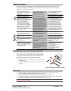
Two removable T-brackets with two 40mm screws.
Additional Required Items
• Phillip screwdriver
• Screws, washers and nuts to attach the Commander to your rack
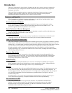
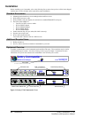
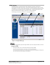
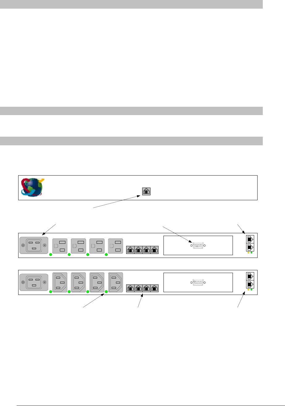
Equipment Overview
A number is printed above each Commander outlet and Pass-Thru port. These numbers may be used in
commands that require a name. See Outlet Naming and Grouping in Chapter 3: Operations for more
information. The power inlet connects the Commander to the electrical power source.
4321
MODEM
4321
PASS-THRU
Serial
Ethernet
ACT LINK
4321
MODEM
4321
PASS-THRU
Serial
Ethernet
ACT LINK
100-120V PT40-H404-1-02
208-240V PT40-H404-2-02
Sentry Commander
Remote Power Manager
TM
Server Technology, Inc.
www.servertech.com
AUX
DB9 male Modem
(For connection to external modem)
RJ45 Serial (RS-232)
RJ45 Ethernet
AC Power Inlet
Outlet Power Status LED RJ12 Pass-Thru
RJ12 AUX
(For connection to optional Environmental Monitor)
Figure 2.1 Sentry PT40 Commander Views
6 • Installation Sentry Commander - PT40
Installation and Operations Manual