


Chapter 8 Menus
101
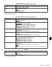
8-3 Extended Menu
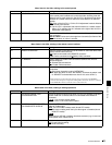
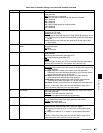
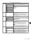
819 AUDIO INPUT SOURCE ARRANGE Enable or disable mixing of the audio signals of channels 1 to 8 into the
audio signals of the same channels recorded on the disc.
Sub-item
1MIXING off
: Do not mix.
on: Mix.
2 CH1 When MIXING is set to “on,” select the audio channels for which mixing
is enabled.
off
: Not selected.
on: Selected.
3 CH2
4 CH3
5 CH4
6 CH5
7 CH6
8 CH7
9 CH8
820 AUDIO OUTPUT CH1/CH2 SELECT Select the signals to be output from the AUDIO OUT 1/3 and AUDIO
OUT 2/4 connectors.
line
: Output the audio channel signals selected with item 824 “just as
they are” from the AUDIO OUT 1/3 and 2/4 connectors.
moni: Output the monitor audio L-channel (CH-1) and monitor audio R-
channel (CH-2) signals from the AUDIO OUT 1/3 and AUDIO OUT 2/4
connectors, respectively.
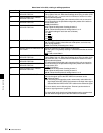
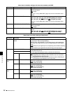
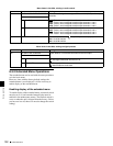
823 NON-AUDIO FLAG PB Control non-audio flags in digital audio output.
Sub-item
1 CH1/CH2 During playback (except E-E mode), set non-audio flags in digital audio
output to the following states.
on: Set to on (data is non-audio)
auto
: Set as follows.
• When data is read from disc and confirmed: Follow the data.
• When data from disc is not confirmed: Maintain current state.
2 CH3/CH4
3 CH5/CH6
4 CH7/CH8
824 ANALOG LINE OUTPUT SELECT Select the analog audio signals (tracks 1 to 8) to be assigned to audio
output channels 1 and 2.
tr1/2
: Tracks 1 and 2 assigned to audio output channels 1 and 2.
tr3/4: Tracks 3 and 4 assigned to audio output channels 1 and 2.
tr5/6: Tracks 5 and 6 assigned to audio output channels 1 and 2.
tr7/8: Tracks 7 and 8 assigned to audio output channels 1 and 2.
Note
When item 820 is set to “moni,” the left channel (CH-1) and right channel
(CH-2) of monitor audio are output from the AUDIO OUT 1/3 and 2/4
connectors respectively, regardless of the setting of this item.
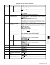
827 AES/EBU AUDIO OUTPUT SELECT Select the audio signals to assign to AES/EBU audio output channels.
Sub-item
1 CH1/CH2 tr1/2
: Tracks 1 and 2 assigned to audio output channels 1 and 2.
tr3/4: Tracks 3 and 4 assigned to audio output channels 1 and 2.
tr5/6: Tracks 5 and 6 assigned to audio output channels 1 and 2.
tr7/8: Tracks 7 and 8 assigned to audio output channels 1 and 2.
2 CH3/CH4 tr1/2: Tracks 1 and 2 assigned to audio output channels 3 and 4.
tr3/4
: Tracks 3 and 4 assigned to audio output channels 3 and 4.
tr5/6: Tracks 5 and 6 assigned to audio output channels 3 and 4.
tr7/8: Tracks 7 and 8 assigned to audio output channels 3 and 4.
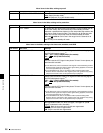
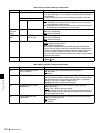
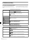
Menu items in the 800s, relating to audio control
Item number Item name Settings