


Chapter 4 Recording/Playback
52
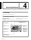
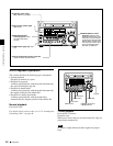
4-1 Recording
In this case, the setting of extended menu item 628 “DF
MODE” is ignored. New time code is recorded in the drop-
frame mode of the last recorded time code on the disc.
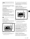
To record with the internal time code
generator synchronized to external time
code
You can record with the internal time code generator
synchronized to time code input from an external device.
Use this method to synchronize the time code generators of
a number of recorders, or to carry out recording
maintaining the synchronization between the source video
and time code.
In this case, the settings of extended menu items 627
“RUN MODE” and 628 “DF MODE” are ignored.
You can synchronize the internal time code generator to
one of the following external time codes.
• VITC input to this unit’s TIME CODE IN connector
• VITC in a video signal input to this unit
• SMPTE RP188 LTC in an SDI signal input to this unit
• i.LINK TC input to this unit’s S400 (i.LINK)
connector
• i.LINK VITC input to this unit’s S400 (i.LINK)
connector
Use the following procedure to synchronize the internal
time code generator according to the type of external time
code.
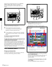
1
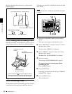
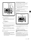
Make either of the following connections and settings.
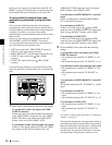
To synchronize to time code input to the TIME
CODE IN connector
Connect the time code output from the external device
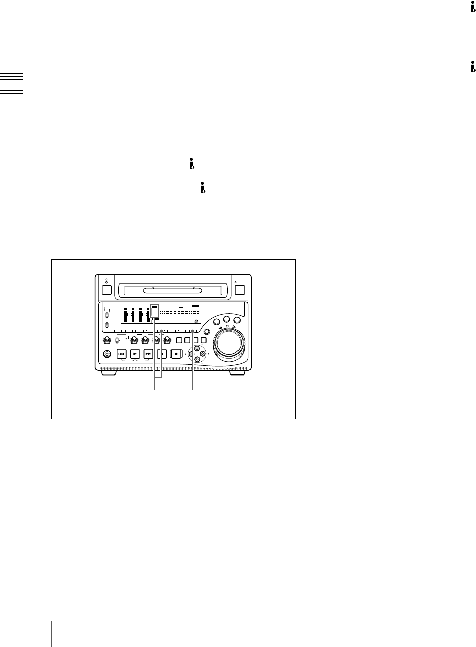
to the TIME CODE IN connector. Press the VIDEO
INPUT SEL button and, while viewing the INPUT
display, select one of SDI, CMPST, or SG.
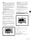
To synchronize to time code in an input video signal
Connect a video signal containing VITC to the VIDEO
IN connector or the SDI IN connector. Press the
VIDEO INPUT SEL button and, while viewing the
INPUT display, select CMPST or SDI.
To synchronize to SMPTE RP188 LTC in an SDI
signal
Connect an SDI signal containing SMPTE RP188
LTC to the SDI IN connector.
To synchronize to i.LINK TC
Connect an i.LINK signal to the S400 (i.LINK)
connector. Press the VIDEO INPUT SEL button and,
while viewing the INPUT display, select i.LINK.
To synchronize to i.LINK VITC
Connect an i.LINK signal to the S400 (i.LINK)
connector. Press the VIDEO INPUT SEL button and,
while viewing the INPUT display, select i.LINK.
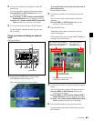
2
Press the MENU button, then make the following
settings.
To synchronize to time code input to the TIME
CODE IN connector
• Set extended menu item 626 “TC MODE” to “ext
regen.”
• Set extended menu item 629 “TC SELECT” to “tc.”
To synchronize to time code in an input video signal
• Set extended menu item 626 “TC MODE” to “ext
regen.”
• Set extended menu item 629 “TC SELECT” to
“vitc.”
To synchronize to SMPTE RP188 LTC in an SDI
signal
Set extended menu item 626 “TC MODE” to “rp188
regen.”
To synchronize to i.LINK TC
• Set extended menu item 626 “TC MODE” to “ext
regen.”
• Set extended menu item 629 “TC SELECT” to “tc.”
To synchronize to i.LINK VITC
• Set extended menu item 626 “TC MODE” to “ext
regen.”
• Set extended menu item 629 “TC SELECT” to
“vitc.”
For details of menu setting operations, see Chapter 8
“Menus” on page 85.
This starts the internal time code generator running in
synchronization with the external time code generator.
Once the internal time code generator is synchronized
with the external time code generator, even if the
external time code generator connection is removed,
the internal time code generator continues to run.
REC
VARIABLE
PRESET
PB
L
MIX
R
MONITOR
NETWORK
LOCAL
REMOTE
ACCESS
PHONES
TOP
F REV F FWD
END
PREV
NEXT
PLAY
AUDI O
MONITOR SEL
METER SEL INPUT CH INPUT SEL
VIDEO
INPUT SEL
COUNTER
SELECT
SUB
CLIP
THUMB
NAIL
SET RESET
SHIFT
EJECT
HOLD
STOP
REC
S
H
U
T
T
L
E
J
O
G
V
A
R
MARK1
ESSENCE
MARK
CLIP
MENU
S.SEL
MARK2
IN OUT
ALL/CH-1 CH-2 CH-3 CH-4
OVER
dB
-12
-20
-30
-40
-60
0
CH
-
15
SG DATA
ANASDI
AE8/EBU
OVER
dB
-12
-20
-30
-40
-60
0
CH
-
26
SG DATA
ANASDI
AE8/EBU
OVER
dB
-12
-20
-30
-40
-60
0
CH
-
37
SG DATA
ANASDI
AE8/EBU
OVER
dB
-12
-20
-30
-40
-60
0
CH
-
48
SG DATA
ANASDI
HOURS MINUTES SECONDS FRAMES
AE8/EBU
VITC VITCCOUNTER REC INHVIUB
EDIT KEY INHREMOTE
[
9P iLINK
]
INPUT
i.LINK
SDI
1/2
5/6
3/4
7/8
625
525
IMX
[
50 40 30
]
DVCAM
4 8 CH
18 24 BIT
CMPST
Y-R,B
SG
ALARM
MONITOR
AUDI O
SYS MENU
MENU
1 2