


52
13. CONNECTIONS
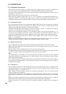
13.1. Equipment Connections
• Use the CPEV-S cable (twisted pair shielded cable) with diameter larger than 0.65 mm (AWG22) for
connection between control terminals. Be sure to connect the shielded cable to the GND terminal.
• The control cable length between the Remote Controller and the farthest Digital Video Recorder must be
shorter than 1.2 km (3,937 ft).
• All connected components must be identical in transmission rate.
• When using the supplied modular cable (3 m (9.8 ft)) for connection to the Digital Video Recorder, the
supplied AC adapter is not required since the power is supplied from the Digital Video Recorder. When
using the Remote Controller’s screwless terminal, connect the supplied AC adapter to supply the power.
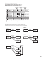
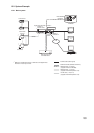
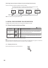
13.1.1. Combination camera
• Up to 16 Combination Cameras can be operated per Digital Video Recorder (up to 9 cameras per 9-channel
Digital Video Recorder). Avoid connecting more cameras than the number of Digital Video Recorder
channels to the Digital Video Recorder’s camera control terminal.
• The Digital Video Recorder must be used to control the Combination Camera. It is impossible to control the
camera by connecting the Remote Controller directly to the camera.
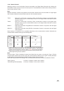
• There are two communications methods of the Combination Camera: Type A and Type B.(Refer to p. 45;
Camera Protocol.) Multiple combination cameras using different communication methods cannot be
connected to a single digital video recorder. Match the communication methods of all connected cameras.
• Match the transmission rate among the combination camera, digital video recorder, and remote controller.
(Refer to p. 49; I/O Speed.)
• Match the Combination Camera’s address to the Digital Video Recorder’s video input number. The camera
number entered at the Remote Controller is the Combination Camera’s address number.
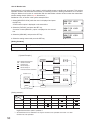
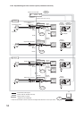
13.1.2. Digital video recorder
• Up to 8 Digital Video Recorders can be cascade-connected and controlled by the Remote Controller.
• When cascade-connecting the Digital Video Recorder, set the termination switch of the last connected
Digital Connector to ON.
• Be sure to select “ON” in the digital video recorder’s controller response setting.
• The Digital Video Recorder’s “DVR-ID” settings must be performed when cascade-connecting the recorder.
For more information, please read the Digital Video Recorder’s instruction manual.
Note
Two setting methods are available: one from the Digital Video Recorder's menu and the other using the
Digital Video Recorder's front-mounted keys. For more information, refer to the operation manual enclosed
with the Digital Video Recorder.
• Do not connect 2 Remote Controllers simultaneously to each Remote Controller Input Terminals A and B, as
they could not be operated correctly. Use the Interface Unit when connecting multiple Remote controllers to
the Digital Video Recorder.
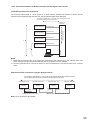
13.1.3. Interface unit
• Up to 4 Remote Controllers can be expanded with the use of the Interface Unit. (Up to 3 controllers when
the RS-232C terminal is in use.) Set the Monitor Lock when connecting multiple Remote Controllers to the
interface unit. (Refer to p.50; Monitor Lock.)
• When multiple connected remote controllers are operated simultaneously, the most recently operated
remote controller takes precedence.
• The transmission rate between the Interface Unit and the Digital Video Recorder is fixed to 38,400 bps.
When using the Interface Unit, set the Digital Video Recorder’s remote control transmission rate to 38,400
bps.
• Make sure to match the transmission rate of all components connected to the Interface Unit. Also, match the
Interface Unit’s DIP switching settings to the Remote Controller’s transmission rate settings.
• When the Interface Unit is used, the power to the Remote Controller is supplied from the supplied AC
adapter.