53
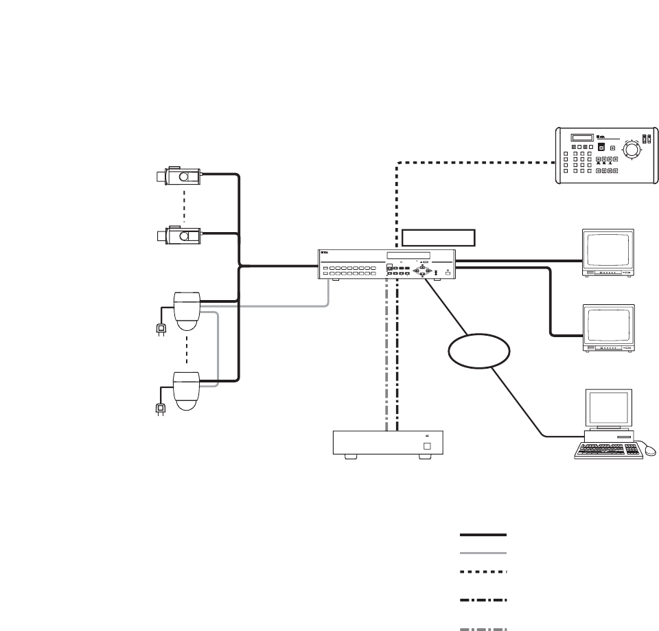
13.2. System Example
13.2.1. Basic system
Color camera
Digital Video Recorder
C-DR091 or
C-DR161 Series
Monitor 1
16
Monitor 2
HDD expansion unit
C-DA1000 Series
DISK
ARRAY
1
PC
Remote Controller
C-RM1000
Live display
only
To AC Mains
Combination
Camera
RS-485
RS-485
RM IN-A
LAN
DVR CONTROL
OUTPUT-A
10BASE-T
100BASE-TX
KEY LOCK
DIGITAL VIDEO RECORDER C-DR161
HD FULL
FAILURE
REC
16
8
15
7
14
6
13
5
12
4
11
3
10
2
9
1ARCHIVE
: CPEV-S 0.65-2C (RS-485 control line)
: Coaxial cable (video signal)
: Modular cable, 3 m (9.8 ft).
(supplied with the C-RM1000)
: Modular cable, 1 m (3.3 ft)
(supplied with HDD expansion unit)
: S-ATA cable, 1 m (3.3 ft)
(supplied with HDD expansion unit)
Match the Combination Camera’s address to the Digital Video
Recorder’s video input number.
*
1
*
1
*
1
Termination: ON


