


Copyright © 2003 TOSHIBA CORPORATION. All rights reserved.
10
IN
ANT
(
75
)
REC OUT
ANT-1 ANT-2
PB
PR
Y
L/
MONO
AUDIO
S-VIDEO
VIDEO 1 VIDEO 2
COLOR
STREAM
HD-1
COLOR
STREAM
HD-2
VIDEO
R
L
AUDIO
VIDEO
R
L
AUDIO
R
PB
PR
Y
L
AUDIO
R
VIDEO
L/
MONO
ON OFF
L
AUDIO
AUDIO
VAR
R R
OUT
CHANNEL IN
AUDIO CENTER
DVI/HDCP IN
R
AUDIO
L
G-LINK
IR OUT
DIGITAL
AUDIO OUT
IEEE1394
1
IEEE1394
2
TheaterNet
TheaterNet
___________
Apple and FireWire are trademarks of Apple Computer, Inc., registered in the U.S. and other countries.
IN
ANT
(
75
)
Rec Out
ANT-1 ANT-2
P
B
P
R
Y
L/
MONO
AUDIO
S-VIDEO
VIDEO 1
VIDEO 2
COLOR
STREAM
HD-1
COLOR
STREAM
HD-2
VIDEO
R
L/'MONO
AUDIO
VIDEO
R
L
AUDIO
R
P
B
P
R
Y
L
AUDIO
R
VIDEO
L/
MONO
ONOFF
L
AUDIO
AUDIO
VAR
R R
OUT
CHANNEL IN
AUDIO CENTER
DVI/HDCP IN
R
AUDIO
L
TheaterLink
DIGITAL
AUDIO OUT
IEEE1394
1
IEEE1394
2
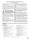
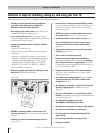
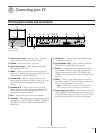
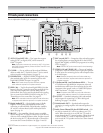
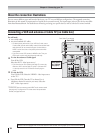
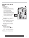
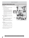
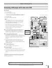
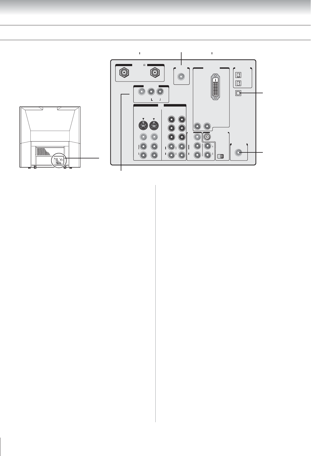
TV back panel connections
For an explanation of cable types, see page 11.
4
5
789
{
{
}
{
1 ANT-1 IN and ANT-2 IN — Two inputs that support
analog (NTSC) or digital (ATSC) off-air antenna or
Cable TV signals.
Note: If you have an antenna only, connect it to ANT-1. If you have
both Cable TV and an antenna, connect the Cable TV to ANT-1 and
the antenna to ANT-2.
2 G-LINK
™
— For use with one of the enclosed IR blaster
cables to enable the TV Guide On Screen
™
device control
and one-touch recording features. See page 25.
3 DVI/HDCP IN — Digital DVI/HDCP single-link video
plus standard audio inputs for connecting devices with
single-link DVI/HDCP output. See page 18.
Note: DVI-D cable carries only video information; separate
audio cables are required for a complete connection.
4 IEEE-1394 — Two bi-directional digital IEEE-1394 (also
known as Firewire
™
) ports for connecting multiple devices
with compressed digital video. Because these ports are
bi-directional, they can be used for playback and recording.
You can control your IEEE-1394 devices using the TV’s
TheaterNet on-screen control bar. See pages 22.
Note: IEEE-1394 cable carries both audio and video information;
no separate audio cables are required for a complete connection.
5 Digital Audio OUT — Optical audio ouput in Dolby
Digital or PCM (pulse-code modulation) format for
connecting an external Dolby Digital decoder, amplifier,
AV receiver, or home theater system with optical audio
input. See page 19.
6 IR OUT — For controlling infrared remote-controlled
devices through the TV. You can connect up to two devices
with one of the enclosed IR blaster cables, and then control
the devices using the TV’s IR pass-through or TheaterNet
™
(on-screen device control) features. See pages 21 and 45.
7 REC (record) OUT — Composite video and audio outputs
for recording down-converted digital off-air feed (ATSC),
digital Cable (QAM), or IEEE-1394 programs to an analog
VCR. See page 17.
Note: The REC OUT jacks cannot be used for timed recordings.
8 VIDEO 1 IN and VIDEO 2 IN — Two sets of standard
(composite) video and standard audio inputs plus optional
S-video inputs for connecting devices with composite video
or S-video output.
Note: Standard (composite) video and S-video cables carry
only video information; separate audio cables are required for a
complete connection.
9 ColorStream HD-1 and ColorStream HD-2 — Two sets
of ColorStream
®
high-definition component video and
standard stereo audio inputs for connecting devices with
component video output, such as a Toshiba DVD player
with ColorStream.
®
See pages 14 and 16.
Note: Component video cables carry only video information;
separate audio cables are required for a complete connection.
0 A/V OUT — Standard (composite) video and standard
audio outputs for connecting a VCR for editing and
dubbing. See page 17 for details.
!¡ Variable Audio OUT — Standard audio ouputs for
connecting an analog amplifier with external speakers. See
page 19.
!™ Audio Center Channel IN plus ON/OFF switch — For
use with an external A/V receiver to enhance your TV’s
audio. When the switch is set to OFF, the TV’s audio is
output through the TV’s internal speakers. When the switch
is set to ON, the TV’s audio is output through the A/V
receiver and the TV’s speakers are used as a center channel.
See page 20.
6
1
}
2 3
}
Chapter 2: Connecting your TV
!¡
{
!º
{
!™
{