


Copyright © 2003 TOSHIBA CORPORATION. All rights reserved.
17
Chapter 2: Connecting your TV
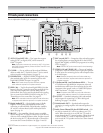
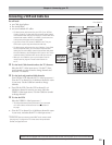
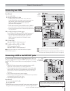
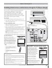
Connecting two VCRs
You will need:
two coaxial cables
two sets of standard A/V cables
• For better picture performance, if VCR 1 has S-video, use an
S-video cable (plus the audio cables) instead of the standard video
cable. However, do not connect both types of video cable to
VIDEO 1 (or VIDEO 2) at the same time or the picture
performance will be unacceptable.
• If VCR 1 has mono audio, connect L/MONO on the TV (VIDEO 1)
to the audio out jack on VCR 1 using the white audio cable only.
• Do not connect the same VCR to the output and input jacks on the
TV at the same time.
To view the antenna or Cable signal:
Turn OFF the VCR. Select the ANT-1 video input source.*
• If you have both an off-air antenna and Cable TV, connect the
antenna to ANT-2 and the Cable TV to ANT-1 (ANT-1 and
VIDEO 1 are the only sources for the TV Guide On Screen
program guide).
To view VCR 1:
Select the VIDEO 1 video input source.*
To dub or edit from VCR 1 to VCR 2:
VCR 2 must select “line IN.”
Select the VIDEO 1 video input source.*
Note: If you have a Cable box, connect the Cable box and splitter to
VCR1 as shown on page 13.
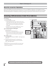
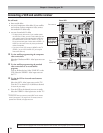
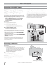
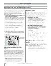
Connecting a VCR to the REC OUT jacks
If you connect an ATSC antenna or digital Cable service to ANT 1 or
ANT 2, or a digital device to one of the IEEE-1394 ports, you can use
the REC OUT jacks to record down-converted programs to an analog
VCR.
Note:
• The REC OUT jacks only output down-converted signals from an ATSC,
digital Cable, or IEEE-1394 source in an analog signal format.
• For the best possible audio/video performance, when using an ATSC, digital
Cable, or IEEE-1394 source, it is recommended that you use the REC OUT
jacks (instead of A/V OUT or VAR AUDIO OUT) to connect to an external
A/V system.
• This connection cannot be used for timed recordings.
• Because of copy protection requirements, the REC OUT jacks may be blocked
during playback of some IEEE-1394 content.
• See “Using the digital tuner hold” on page 61.
You will need:
one set of standard A/V cables
one coaxial cable
The Video OUT jack does not output the POP picture.
The AUDIO OUT jacks can output the sound of either the Main or
POP picture (see “Selecting the AUDIO OUT sound” on page 79).
b
a
IN
ANT
(
75
)
REC OUT
ANT-1 ANT-2
P
B
P
R
Y
L/
MONO
AUDIO
S-VIDEO
VIDEO 1 VIDEO 2
COLOR
STREAM
HD-1
COLOR
STREAM
HD-2
VIDEO
R
L
AUDIO
VIDEO
R
L
AUDIO
R
P
B
P
R
Y
L
AUDIO
R
VIDEO
L/
MONO
ON OFF
L
AUDIO
AUDIO
VAR
R R
OUT
CHANNEL IN
AUDIO CENTER
DVI/HDCP IN
R
AUDIO
L
G-LINK
IR OUT
DIGITAL
AUDIO OUT
IEEE1394
1
IEEE1394
2
TheaterNet
TheaterNet
IN from ANT
VIDEO AUDIO
OUT to TV
CH 3
L
R
L
R
LR
CH 4
IN
OUT
IN from ANT
VIDEO AUDIO
OUT to TV
CH 3
L
R
L
R
LR
CH 4
IN
OUT
VCR1 (plays)
From
antenna
or Cable
TV
VCR2 (records)
b
a
IN
ANT
(
75
)
REC OUT
ANT-1 ANT-2
P
B
P
R
Y
L/
MONO
AUDIO
S-VIDEO
VIDEO 1 VIDEO 2
COLOR
STREAM
HD-1
COLOR
STREAM
HD-2
VIDEO
R
L
AUDIO
VIDEO
R
L
AUDIO
R
P
B
P
R
Y
L
AUDIO
R
VIDEO
L/
MONO
ON OFF
L
AUDIO
AUDIO
VAR
R R
OUT
CHANNEL IN
AUDIO CENTER
DVI/HDCP IN
R
AUDIO
L
G-LINK
IR OUT
DIGITAL
AUDIO OUT
IEEE1394
1
IEEE1394
2
TheaterNet
TheaterNet
IN from ANT
VIDEO AUDIO
OUT to TV
CH 3
L
R
L
R
LR
CH 4
IN
OUT
TV
VCR
From
ATSC antenna
or digital Cable
Connect the IR
blaster cable to
the G-LINK jack
(see page 25)
_____________
* To select the video input source, press INPUT on the remote control (see page 61).
To program the TV remote control to operate other devices, see pages 30 to 33.
The unauthorized recording, use, distribution, or revision of television
programs, videotapes, DVDs, and other materials is prohibited under the
Copyright Laws of the United States and other countries, and may subject
you to civil and criminal liability.