


CIRCUIT DESCRIPTIONS
PV154 - 923-03506 3-13 ZP26/28 - SERVICING
in the EEPROM, such as the window for Closed Caption
detection.
Data and Clock lines are SDA1 from pin (2) of the
Microprocessor to pin (5) of the EEPROM and SCL2
from pin (3) of the Microprocessor to pin (6) of the
EEPROM. Data travels in both directions on the Data
line.
FLEX CONVERTER UC01
The projection television is capable of displaying NTSC
as well as ATSC (DTV) including HD (High Definition).
The Flex Converter is responsible for receiving any
video input and converting it to 33.75 Khz output.
This output is controlled by sync and by the customer’s
menu and how it is set up. The set up can be 4X3 or
16X9 for DTV, or letterbox. This set also has something
called “Through Mode”. This bypasses the Flex
Converter completely and inputs the 1080i signal
directly to the Rainforest IC. The Rainforest IC then
outputs the signal directly. The Flex Converter can
take any NTSC, S-In, Component, NTSC or Progressive,
Interlaced, 480I, 720P, 1080i signal.
Control for the Flex Converter is Clock, Data and Enable
lines. Clock, Data and Enable lines for the Flex Converter
are output from the Microprocessor at pins (45) Data
and (46) FCENABLE. The FCENABLE line is routed
through the PFC1 connector pin 12 and the FCDATA
line is routed through the PFC1 connector pin 11.
The Clock line must be routed through the Level Shift
IC I004 to be brought up to 5V. The Microprocessor
output for Clock is pin 58, it arrives at I004 at pins
(3) Clock and is output at pins (17). It arrives at the
Flex Converter through the PFC1 connector pin 10.
DAC1 I006
This Digital to Analog converter acts as an extension of
the Microprocessor. Sometimes called an Expansion IC.
The purpose of this IC is to reduce the number of pins,
(fan out) of the Main Microprocessor I001. The Main
Microprocessor sends Clock and Data via I
2
C bus to the
DAC1 IC. The output from the Microprocessor is pin (2)
SDA1 and (3) SCL1 which arrives at the DAC1 IC I006 at
pins (5 and 6) respectively.
DAC3 I007
This Digital to Analog converter acts as an extension of
the Microprocessor. Sometimes called an Expansion IC.
The purpose of this IC is to reduce the number of pins,
(fan out) of the Main Microprocessor I001. The Main
Microprocessor sends Clock and Data via I
2
C bus to the
DAC3 IC. The output from the Microprocessor is pin (2
(SDA1) and 3 (SCL1) which arrives at the DAC3 IC at
pins 5 and 6 respectively.
LEVEL SHIFT I004
The Microprocessor operates at 3.3Vdc. Most of the Cir-
cuits controlled by the Microprocessor operate at 5Vdc.
The Level Shift IC steps up the DC voltage to accommo-
date.
• Pin 4 outputs a Clock, used by the Flex Converter
• Pin 11 outputs Error Mute signal (ERRMUTE), used
to mute the Out to Hi-Fi jacks on the SRS PWB.
• Pin 13 outputs a Front Speaker Off signal (FSPOFF),
used to turn off the internal speakers.
3D Y/C I301
(IC mounted directly on the Signal PWB)
The 3D Y/C IC is a Luminance/Chrominance separator, as
well as a 3D adder. Separation takes place digitally. Us-
ing advanced separation technology, this module sepa-
rates using multiple lines and doesn’t produce dot pat-
tern interference or dot crawl. The 3D effect is a process
of adding additional emphasis signals to the Luminance
and Chrominance. These signals relate specifically to
transitions. Transitions are the point where the signal
goes from dark to light or vice versa. The 3D adds a
little more black before the transition goes to white
and a little more white just before it gets to white. It
also adds a little more white just before it goes dark
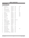
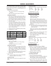
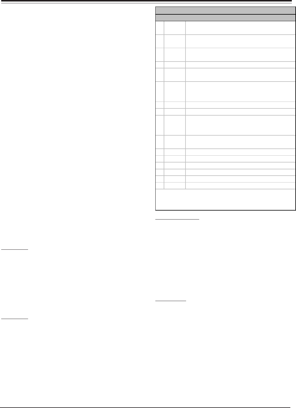
PIN DESC FUNCTION
1Busy
Receives Busy from DCU stopping Microprocessor
from responding to Remote commands.
2ST Det
Receives the Low from the Main Tuner indicating
Stereo signal received.
3MTS
Places the Main Tuner into MTS mode if Stereo MTS
Detected by Microprocessor
4 F Mono Places the Main Tuner into Forced MONO mode
5Ant
Switches the antenna block into Antenna A or
Antenna B when selected.
6Cut Off
In Service Mode, if Set Up is selected, outputs High
to collapse Vertical circuit and inhibit Vert. Sweep
Loss Detection
7 Magic Sw Places the Unit into HD Focus Mode.
8 Gnd Ground
9D Size
During HD Focus and Sensor Initialize, the H and V
Size has to be increased slightly for Sensor striking
purposes.
10 SAP Det
Receives the Low from the Main Tuner indicating SAP
signal received.
11 Gnd Ground Not Used
12 Gnd Ground Not Used
13 STBY 5V Standby +5 Volt input.
14 SDA1 Serial Data from Microprocessor
15 SCL1 Serial Clock from Microprocessor
16 SBY +5V Vcc SBY +5V
DAC1 I006 Pin Descriptions
NOTE: Pin 1 Busy and Pin 9 D Size works as a tri-data-level-input.
The Digital Convergence Module is active during Service Adjustment
(DCAM), HD Focus and/or Sensor Initialize.