


PV154 - 923-03506 ZP26/28 - SAFETY
- iii -
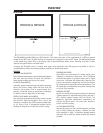
PRODUCT SAFETY SERVICING GUIDELINES FOR AUDIO-VIDEO PRODUCTS
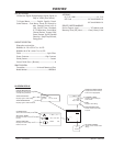
HOLD-DOWN CIRCUIT INFORMATION
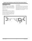
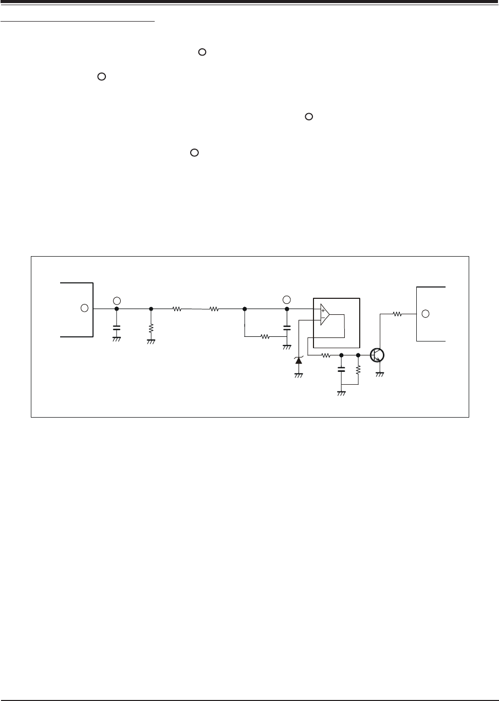
NORMAL CONDITION
In normal condition, the DC voltage at point is ap-
proximately 4.88V through pin 1 of P1407 (HV Block).
The voltage at point is approximately 4.86V. The
voltage of pin 5 of IC404 is lower than the voltage of
pin 6 (5.1V). The voltage of pin 7 is 0V and the transis-
tor Q403 is off.
ABNORMAL CONDITION
In abnormal condition, the voltage of point is much
higher than normal voltage. The voltage of pin 5 of IC404
is 24V and the transistor Q403 is on. Therefore, pin 1 of
IC401 receives a voltage causing the hold-down circuit
to be active. This results in the frequency of the hori-
zontal oscillation and deflection to be stopped and then
the set goes into stand-by mode.
a
a
b
b
C1439
1
a
R1435
R1455
R493
b
J8
C417
ZD406
(5.1V)
R411
R410
IC404
HPROT
C455
R491
Q403
IC401
1
5
6
7
P1407 (H.V. Block)
X-RAY PROTECTION
Check the X-Ray protection circuit using the following
steps. Turn the set on and input a color bar signal. Check
the B+ voltage to make sure it is correct. If B+ is 148 to
160 VDC, the power circuit is defective. To check the
operation of the hold-down circuit, apply DC 6V (+- 0.5)
to point . If there is no raster, the set is operating
properly and doesn’t need to be repaired.