


SERVICE ADJUSTMENTS
PV154 - 923-03506 3-21 ZP26/28 - SERVICING
OK, repeat steps 5 through 12.
12. Press the MENU key on the remote to Exit Service
Menu. Remember: When adjusting the Screen con-
trols, after the Cut Off adjustment has been com-
pleted, never adjust the controls clockwise. Al-
ways adjust counter clockwise. This lengthens tube
life.
CHASSIS HORIZONTAL PHASE (FINE) ADJUSTMENT
ADJUSTMENT PREPARATION:
1. Cut Off, DCU Phase adjustments should be finished.
2. Video Control: Brightness 90%, Contrast Max.
ADJUSTMENT PROCEDURE NORMAL MODE
3. Receive any NTSC crosshair signal.
4. Screen Format is NORMAL.
5. Press the SERVICE ONLY switch on the convergence
PWB and display the Digital Convergence Cross-
hatch pattern.
6. Mark the center of the Digital Convergence Cross-
hatch Pattern with finger and press the SERVICE
ONLY switch to return to normal mode.
7. Enter the I
2
C Bus alignment menu and select Item
H POSI and adjust the data so that the center of
Video matches the location of the Digital Cross-
hatch pattern noted in step {4}.
8. Exit from the I
2
C Menu.
16X9 HD Mode Adjustment: NOTE: I2C Service Menu
Can Not be entered in the 16X9 HD Mode.
9. Receive any 2.14H signal.
10. Change Screen Format 16X9 HD mode.
11. Press the SERVICE ONLY switch on the deflection
PWB and display the Digital Convergence Cross-
hatch pattern.
12. Mark the center of the Digital Convergence Cross-
hatch Pattern with finger and press the SERVICE
ONLY switch to return to normal mode.
13. Enter the I
2
C Bus alignment menu and select Item
[9] H POSI
14. Press SELECT key on R/C. (H POSI option is changed
to HD mode. H POSI H appears). H POSI of 16X9
HD mode data can be changed.
15. Adjust the data up or down slightly.
16. Exit from the I
2
C Menu.
17. Change Screen Format to 16X9 HD mode.
18. Confirm that the Center of Video matches the Cen-
ter of the DCU Crosshatch determined in step (12).
19. If center is not correct, Repeat steps (12) through
(18) until center is matched.
NOTE: To enter the I
2
C Bus alignment menu, with Power
Off, press the INPUT button and hold it down, then
press the POWER button. I
2
C adjustment menu will
appear.
CHASSIS INTELLISENSE “PATTERN SET UP”
NOTE: This instruction should be applied when a new DCU
is being replaced.
NOTE: This instruction shows how to set up the pattern
position for Intellisense. Each model has a specific
set up pattern position.
ADJUSTMENT PREPARATION:
· Receive NTSC RF or Video Signal.
· With Power Off, Press and HOLD the SERVICE ONLY
button on the Convergence/Focus PWB, then press
the Power On/Off button and release, picture
appears, then release Service Button to bring up
Internal Crosshatch.
NOTE: After entering the DCAM, each press of the Service
Only Switch will toggle between Video mode and
DCU grid.
· Press the C SKIP (twice) to read the old ROM data,
DCU Grid returns to normal with convergence cor-
rection.
ADJUSTMENT PROCEDURE
1. Make sure the Remote is in TV mode.
2. Press the (-) key on R/C. (One additional line ap-
pears near the top and bottom.
3. Change Remote to VCR mode.
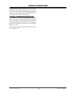
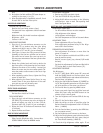
4. Press the (-) key. The PATTERN mode is displayed
as shown on the right.———>
5. Change Remote back to TV mode.
6. Use the 6 Key to rotate Arrow. Arrow rotates clock-
wise with each press on the 6 Key.
7. Use the following Keys to switch color of patterns.
o Display : GREEN
o 0 : RED
o Source : BLUE
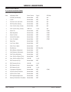
8. Press the ? or ? Cursor to change the Pattern Po-
sition Data in horizontal Direction to match the
chart below.
9. Press the [?] or [?] Cursor keys to change the Pat-
tern Position Data in Vertical Direction to match
the chart below.
10.Press the MULTI key 2 times to write the changed
data into EEPROM. o First press, ADJ PAT-
TERN ROM WRITE ? is displayed for alarm. o
Second press writes data into EEPROM. Green dots
appear after completion of operation.
11.Press the MUTE button 2 times to return to the
DCU grid.
12. Power set off.