


CIRCUIT DESCRIPTIONS
PV154 - 923-03506 3-14 ZP26/28 - SERVICING
and a little more dark just before it arrives. This gives
the impression that the signal pops out of the screen
or a 3D effect.
The Microprocessor communicates with the 3D Y/C IC
via I
2
C bus data and clock. The communications ports
from the Microprocessor are pins 59 (SDA2) and 60
(SCL2) to the 3D Y/C I301 pins (59 and 60) respec-
tively.
The Microprocessor also is able to turn on and off cir-
cuits within the 3D Y/C circuit determined by customer
menu set-up.
MAIN VIDEO CHROMA I501 (PREPARATION IC)
The Main Video Chroma IC processes the video and chroma
from the 3D Y/C circuit for the main picture and pre-
pares it for the Flex Converter. It converts video into Y
and chroma into Cr/Cb (NTSC Only). Communication from
the Microprocessor via pins 59 (SDA2) and 60 (SCL2) to
I501 pins (34 and 33) respectively.
RAINFOREST IC01 (VIDEO/CHROMA PROCESSOR)
The Video Processing IC (Rainforest) is responsible for
controlling video/chroma processing before the signal
is made available to the CRTs. Some of the emphasis
circuits are controlled by the customer’s menu and some
of them are controlled by WEAK SIGNAL in Zenith Mod-
els which is AI, (Artificial Intelligence).
Communication from the Microprocessor via pins (59)
SDA2 and (60) SCL2 to the Rainforest IC pins (31 and
30) respectively.
ON THE TERMINAL PWB
A/V SELECTOR IX01
The A/V Selector IC is responsible for selecting the in-
put source for the Main Picture as well as the source for
the PinP or Sub picture. Communication from the Mi-
croprocessor via pins (2) SDA1 and (3) SCL1 to the PST1
connector pins (5 and 4) respectively then to IX01 pins
(34 and 33) respectively.
SUB VIDEO CHROMA IX03
The Sub Video Chroma IC processes the video and chroma
for the Sub or PinP picture. It converts Luminance into
Y and Chroma into Cr/Cb (NTSC Only). Communication
from the Microprocessor via pins (59) SDA2 and (60)
SCL2 to connector PST1 pins (8 and 7) to IX03 pins (34
and 33) respectively.
MAIN Y PR/PB SELECTOR IX04
Any input that is not already in the Y Pr/Pb or Y Cr/Cb
state, will have be converted to this state by I501.
The Main Y Pr/Pb Selector IC selects the appropriate
input between the Tuner, AV Inputs, S-Inputs or Com-
ponents. Communication from the Microprocessor via
pins (59) SDA2 and (60) SCL2 to connector PST1 pins
(8 and 7) to IX04 pins (31 and 30) respectively.
SUB Y PR/PB SELECTOR IX04
Any Sub input that is not already in the Y Pr/Pb or Y Cr/
Cb state, will have be converted to this state by IX03.
The Sub Y Pr/Pb Selector IC selects the appropriate in-
put between the Tuner, AV Inputs, S-Inputs or Compo-
nents. Communication from the Microprocessor via pins
(59) SDA2 and (60) SCL2 to connector PST1 pins (8 and
7) to IX05 pins (31 and 30) respectively.
FRONT AUDIO CONTROL IC IA01
Audio control is performed by this IC. Selection for dif-
ferent Audio modes, volume, bass, treble. The Main Mi-
croprocessor sends Clock and Data via I
2
C bus to this
IC. The output from the Microprocessor is pins (59)
SDA2 and (60) SCL2 respectively then through the con-
nector PSU1 pins (2 and 1) which arrives at IA01 at
pins (4 and 5) respectively.
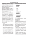
Microprocessor Data Communications circuit diagram.
The Microprocessor must keep in communication with
the Chassis to maintain control over the individual cir-
cuits. Some of the circuits must return information as
well so the Microprocessor will know how to respond to
different requests.
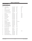
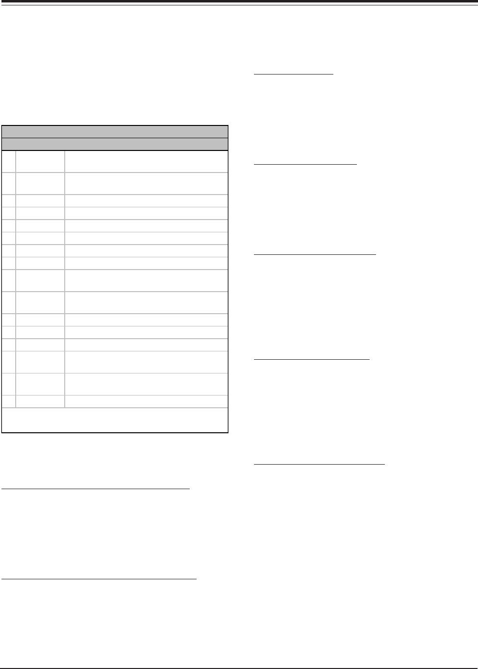
PIN DESC FUNCTION
1 Sig Det Detects active Sync from Component Y signal
for 3 or 4
2 IR Det Detects IR from Remote for Auto Link Remote
Set Up. (Not in Zenith Chassis)
3 P Vol Activates SoundRite determined by Customer
4 AC3 Info T3 (Factory Use)
5 FH Det Out 1 T3 (Factory Use)
6 FH Det Out 2 T3 (Factory Use)
7 FC Blue Back T7 (Factory Use)
8 Gnd Ground
9 Magic Sw In Not Used in Zenith Chassis (No Switch on Front
Control Panel)
10 IN5DET Detect Pr/Cr plug insertion for Component 4
input, if none then Composite is determined.
11 Gnd Ground Not Used
12 Gnd Ground Not Used
13 Gnd Ground Not Used
14 SDA Data I2C communications between DAC2 and
Microprocessor
15 SCL Clock I2C communications between DAC2 and
Microprocessor
16 Vcc IC B+. (STBY +5V).
DAC3 I007 Pin Descriptions
NOTE: Pin 2 The IR pulse from the Remote Control is monitored
when Auto Link is set.