


10
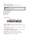
1.4.4.1 Basic Devices
• Cameras
Connect the video output of each video camera or composite video source to the
CH1 ~ CH4 connectors.
• VGA monitor
Connect a VGA monitor to the VGA OUT connector of the DVR unit to use as a
display for video surveillance and playback.
• Power adapter
Plug the provided 110V AC or 220V power adapter into the DVR unit's power
socket.
1.4.4.2 Optional Devices
• Television monitor
Use a BNC-to-RCA adapter to connect a regular TV monitor to the DVR unit's
VIDEO OUT connector.
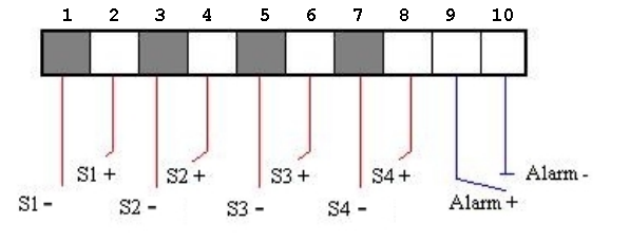
• Sensors and alarm device
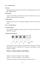
Connect up to four sensor devices to the terminals that are numbered 1 to 8 at the
back panel. Each pair of terminals is for the ground (-) and positive (+) input
voltage. For instance:
Terminal 1 : Connect to the ground (-) wire of Sensor 1
Terminal 2 : Connect to the positive (+) wire of Sensor 1
....
....
Terminal 7 : Connect to the ground (-) wire of Sensor 4
Terminal 8 : Connect to the positive (+) wire of Sensor 4
Connect an alarm device to the terminals that are numbered 9 and 10: