


18 en | Quick install Divar 700 Series
F.01U.246.471 | v3.6 | 2011.11 Installation and Operation manual Bosch Security Systems
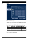
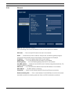
3 Quick install
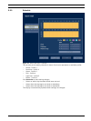
To get the unit quickly operational, make the connections described below and then enter the
relevant data in the Quick install menu.
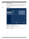
The Quick install menu appears the first time the unit is started. When the relevant
information is entered, the unit will be operational.
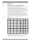
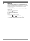
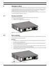
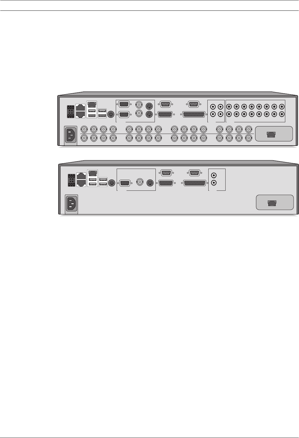
3.1 Connections
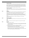
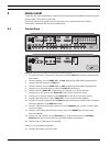
Figure 3.1 Back panel connections for hybrid and network versions
1. For hybrid versions, connect the cameras to the BNC Video in connectors (automatically
terminated).
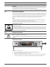
2. Connect monitor A to the CVBS, Y/C, or VGA (supporting 1280x1024) output MON A.
3. Connect the USB mouse to a USB port.
4. Connect monitor B to the CVBS, Y/C, or VGA (supporting 1024x768) output MON B*.
5. Connect up to 16 audio signals to the RCA Audio in connectors*.
6. Connect the RCA Audio out connector(s) to a monitor or an audio amplifier.
7. Connect up to 16 inputs to the Alarm I/O via the 25-pin connector board.
8. Connect up to 4 alarm outputs to the Alarm I/O via the 25-pin connector board.
9. Connect the malfunction output (MAL OUT) via the screw terminal adapter.
10. Connect an Intuikey keyboard to the KBD in socket and connect the terminator (supplied
with the keyboard) to the KBD out socket.
11. Connect a Bosch pan/tilt/zoom control unit to the Biphase port (via the 15-pole D-type
connector board).
12. Connect a third-party pan/tilt/zoom control unit to the RS485 port (via the screw
terminal adapter).
13. Connect to your network via the Ethernet port. (Some versions have a Secondary
Ethernet port which can be used as a separate network connection.)
14. Connect your IP cameras to the network.
Switch on all connected equipment.
15. Connect the power cord to the unit.
KBD in
KBD out
IR ext
VGA CVBS Y/C Biphase
Com 1 Com 2
Alarm I/O
A
B
AA
BB
- | + | G
RS
485
MAL
OUT
N0 | C | NC
Video in
Video out
Video in
Video out
Video in
Video out
1234
1234
5678
5678
9101112 13141516
9101112 13141516
AC
USBUSB
Ethernet
Audio out Audio in
AB
L
R
13579111315
2 4 6 8 10 12 14 16
Monitor out
Secondary Ethernet
KBD in
KBD out
IR ext
VGA CVBS Y/C Biphase
Com 1 Com 2
Alarm I/O
- | + | G
RS
485
MAL
OUT
N0 | C | NC
AC
USBUSB
Ethernet
Audio out
A
L
R
Secondary Ethernet
Monitor out