


24 en | Hardware setup Divar 700 Series
F.01U.246.471 | v3.6 | 2011.11 Installation and Operation manual Bosch Security Systems
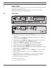
4 Hardware setup
This chapter contains detailed information about the hardware installation and connection of
external equipment to the unit. The connector types and their pin signals are described. Most
of the connectors are located at the rear panel of the unit. For convenience, a USB port is
located on the front of the unit to connect a mouse or memory device.
All the input/output ports are Safety Extra Low Voltage (SELV) circuits. SELV circuits should
only be connected to other SELV circuits.
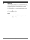
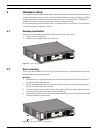
4.1 Desktop installation
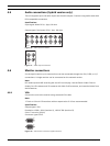
Place the unit on a stable, flat surface. Install the two silver side covers:
1. insert a cover on each side.
2. Slide the cover towards the front of the unit.
Figure 4.1 Side cover installation
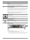
4.2 Rack mounting
The unit can be mounted in a 19-inch rack. A rack mounting kit is supplied with the unit that
includes two rack mounting brackets.
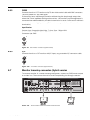
Mounting
1. Remove the four cross head screws (two on each side) located near the front panel on
the right and left side of the unit.
2. Secure the supplied brackets to each side using the same four cross head screws (two
on each side) that were just removed.
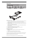
3. To install several units directly on top of each other, remove the rubber feet from under
the unit by prying them loose with a small screwdriver.
4. Install the unit into the rack using the hardware supplied with the rack and following the
rack manufacturer’s instructions.
Figure 4.2 Securing the rack mounting bracket