


Divar 700 Series Hardware setup | en 37
Bosch Security Systems Installation and Operation manual F.01U.246.471 | v3.6 | 2011.11
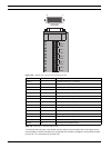
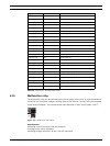
Table 4.8 External I/O - 25-pole D-type socket
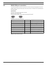
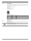
4.15 Malfunction relay
The malfunction relay will be activated upon critical system errors such as, high temperatures
inside the unit, excessive voltages, missing disks or disk failures. Connect using the supplied
screw terminal adapter. The recommended cable diameter is AWG 28-16 (0.08-1.5 mm
2
).
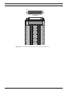
Figure 4.19 Malfunction relay output
Specifications
Switching current (resistive): 500 mA maximum
Carrying power: 10 VA maximum
Switching voltage (resistive): 30 VAC / 40 VDC maximum
Signal name Pin number Description
Alarm_in_1 1 Alarm input 1
Alarm_in_2 2 Alarm input 2
Alarm_in_3 3 Alarm input 3
Alarm_in_4 4 Alarm input 4
Alarm_in_5 5 Alarm input 5
Alarm_in_6 6 Alarm input 6
Alarm_in_7 7 Alarm input 7
Alarm_in_8 8 Alarm input 8
Alarm_in_9 9 Alarm input 9
Alarm_in_10 10 Alarm input 10
Alarm_in_11 11 Alarm input 11
Alarm_in_12 12 Alarm input 12
Alarm_in_13 13 Alarm input 13
Alarm_in_14 14 Alarm input 14
Alarm_in_15 15 Alarm input 15
Alarm_in_16 16 Alarm input 16
Relay1_A 17 Relay 1 output pole 1
Relay1_B 18 Relay 1 output pole 2
Relay2_A 19 Relay 2 output pole 1
Relay2_B 20 Relay 2 output pole 2
Relay3_A 21 Relay 3 output pole 1
Relay3_B 22 Relay 3 output pole 2
Relay4_A 23 Relay 4 output pole 1
Relay4_B 24 Relay 4 output pole 2
System ground 25 Chassis ground
- | + | G
RS
485
MAL
OUT
N0 | C | NC
- | + |
G
RS
4
8
5