


32 en | Hardware setup Divar 700 Series
F.01U.246.471 | v3.6 | 2011.11 Installation and Operation manual Bosch Security Systems
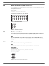
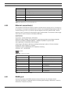
Table 4.3 Keyboard out - RJ11 socket (KBD out)
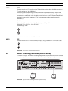
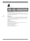
4.10 Ethernet connection(s)
The standard RJ-45 Ethernet socket is used to connect the unit directly to a PC, IP camera, or
to a network. To connect to a network hub or switch, use a straight-through network cable. To
connect directly to a PC or IP camera, use the supplied cross-over network cable. Consult
with your local IT personnel for the specific type of cable needed. The maximum cable length
from node to node is limited to 100 meters (300 feet).
Specifications
Connection: 10/100/1000 BaseT, IEEE 802.3
Differential signal voltage: ± 2.8 V maximum, inputs have transient overvoltage protection
Ethernet port details: IEEE 802.3/802.3u - 100Base-TX/10Base-T physical layer
Auto negotiation: 10/100/1000, full/half duplex
Cable length: 100 meters (100 ohm unshielded twisted pair cable or 150 ohm shielded
twisted pair cable, category 5 or higher).
Impedance: built-in compensation for impedance matching
Indicators: ACT, 10/100/1000
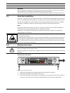
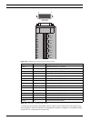
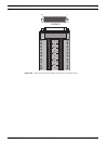
Figure 4.14 Ethernet connector
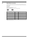
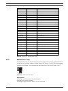
Table 4.4 LAN - RJ-45 Ethernet socket
4.11 RS485 port
Connect third-party controllable cameras to the unit for pan, tilt, and zoom control.
(The Pelco D protocol is supported with the following baud settings: 2400 baud; 1 start bit;
8 data bits; 1 stop bit; no parity.)
Pin number Signal
1 No connection
2 System ground
3 Keyboard minus line
4 Keyboard plus line
5 System ground
6 No connection
Signal name Pin number Description
LAN_TX + 1 Ethernet transmit line plus
LAN_TX - 2 Ethernet transmit line minus
LAN_RX + 3 Ethernet receive line plus
N/C 4 No connection
N/C 5 No connection
LAN_RX - 6 Ethernet receive line minus
N/C 7 No connection
N/C 8 No connection
ETHERNET