


34 en | Hardware setup Divar 700 Series
F.01U.246.471 | v3.6 | 2011.11 Installation and Operation manual Bosch Security Systems
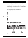
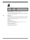
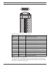
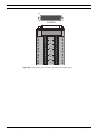
Figure 4.16 Biphase port connector and connection board
Table 4.6 Control port - 15-pole D-type socket
To communicate with the controllable camera, select a port number that is the same as the
input number to which the camera is connected (for example, configure a controllable camera
to port 16 if it is connected to channel 16).
Signal name Pin number Description
Code 1 - 1 Biphase control ch. 1 (minus)
Code 1 + 2 Biphase control ch. 1 (plus)
Shield 3 System ground/cable shield
Code 2 - 4 Biphase control ch. 2 (minus)
Code 2 + 5 Biphase control ch. 2 (plus)
Shield 6 System ground/cable shield
Code 3 - 7 Biphase control ch. 3 (minus)
Code 3 + 8 Biphase control ch. 3 (plus)
Shield 9 System ground/cable shield
Code 4 - 10 Biphase control ch. 4 (minus)
Code 4 + 11 Biphase control ch. 4 (plus)
Shield 12 System ground/cable shield
Code 5 - 13 Biphase control ch. 5 (minus)
Code 5 + 14 Biphase control ch. 5 (plus)
Shield 15 System ground/cable shield
+
-
SHIELD
CTRL 1
SHIELD
+
-
SHIELD
CTRL 2
+
-
SHIELD
CTRL 3
+
-
SHIELD
CTRL 4
+
-
SHIELD
CTRL 5
8
1
9
15
BIPHASE