


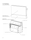
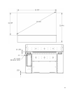
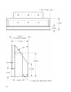


124
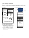
7.4 Connector Diagrams
These are connector diagrams with pin designations. All connectors on these pages are shown looking
at them from the outside, not from the solder side. These diagrams look at the outside of the connec-
tor, as the cable sees it, not the wiring side.
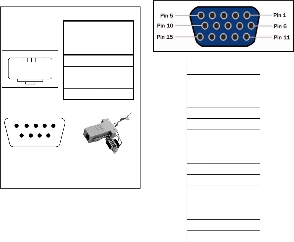
RS232 adapter
The cable must be wired straight-thru. You can
tell if a cable is wired straight-thru by looking at its
two ends side-by-side.
1. Hold the cable ends next to each other, both ends
pointing away from you. Have the clips on both
connectors pointing down so you can’t see them.
2. If the color of the wires on the two connectors is
the same, left to right, the cable is straight-thru.
The order of the colors doesn’t matter, as long as
they are both the same.
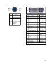
DB15 standard VGA connector
Yellow wire pin 3
Black wire pin 2
Green wire pin 5
RJ45 9-pin
63
55
32
1
23
4
6798
5
The wiring shown for this
adapter is correct for
straight-thru network
cables.
18
RJ45 looking into the
socket.
This little 9-pin to RJ45 adapter is available
unwired from many computer or electronic
stores. Get one with a female 9-pin connector.
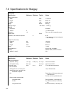
Pin Signal
1Analog Red Out
2Analog Green Out
3Analog Blue Out
4Not connected
5 Ground
6 Ground
7 Ground
8 Ground
9 +5V (DDC)
10 Ground
11 Not connected
12 SDA (DDC)
13 TTL Horizontal Sync
14 TTL Vertical Sync
15 SCL (DDC)