


Installation Procedure 3098 Technical Manual
2-2
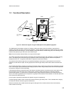
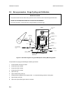
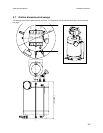
2.3.2 Connections
There are four connections that need to be made to the 3098: three gas pipeline connections and one electrical
connection through an IP rated cable gland. The gas pipeline connections take the form of ¼” Swagelok bulkhead fittings,
and are used for the gas input, gas output and pressure relief lines.
Each connection is labelled.
Caution: Connecting the gas input line to the wrong bulkhead fitting might result in damage.
A 7812 gas density meter is used as the measuring instrument in the 3098 and needs to be connected inside the
enclosure. All wiring should be connected through the cable gland to maintain the enclosure’s overall protection to dust
and water ingress.
At all stages during calibration and operation, the 3098 is designed to function with the enclosure sealed. This allows the
unit to operate in the condition of thermal equilibrium, which is essential for accurate measurement.
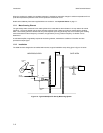
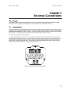
2.4 Electrical Connections and Safety Barriers / Galvanic Isolators
When the 3098 is mounted in a hazardous area, the electrical connections to the meter must conform to stringent
conditions. For electrical connections between the meter and its associated flow computer/signal converter, reference
must be made to safety instruction booklet 30985018/SI.
Electrical cable connection to the 3098 is made to the terminal block inside the resonator electronics housing (i.e. inside
the enclosure). Poor connection to the terminals will prevent correct operation but will not damage the unit - provided that
safety barriers or galvanic isolators are included in the circuit for hazardous areas or the maximum power supply does not
exceed the 33V maximum limit (as described in chapter 3).
The power supplied to the meter terminals should be in the range of 15.5 to 33Vd.c with the average current drawn by the
unit being <20mA. If the current consumption exceeds this value, the polarity of the connections should be checked.
A full description of how to connect the 3098 to a signal converter/flow computer is given in Chapter 3.
2.5 Reference Chamber Pressure Determination
Once the 3098 has been placed in its fixture and all relevant pipework and electrical connections made, the reference
chamber pressure needs to be determined.
The gas type and reference chamber pressure define the ‘controlled condition’ at which the unit allows gas to flow and
establishes a direct relationship between density and the specific gravity of the sample gas.
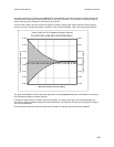
The choice of reference chamber gas pressure is dependent upon 3 factors:
1. The span of specific gravity to be measured.
2. The expected change in sample gas supercompressibility, Z.
3. The accuracy required.