


Electrical Connections 3098 Technical Manual
3-2
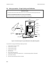
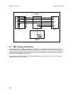
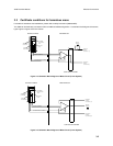
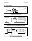
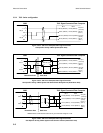
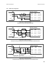
INTERCONNECT PCB
78121503
TERMINAL PCB
78121502
SPOOLBODY
78121201
AMPLIFIER PCB
78121501
PICK UP
COIL
DRIVE
COIL
BN PL1
13 20
2
BN
BN
I/P +
R PL2
14 19
3
O
R
I/P -
O PL5
16 18
4
R
O
O/P +
Y PL6
15 17
5
B
Y
O/P -
R PL3
22
V +
G PL4
21
V -
23
12 4 3
- B+ -
SIG BSIG A
O PL7
FREQ. OUT
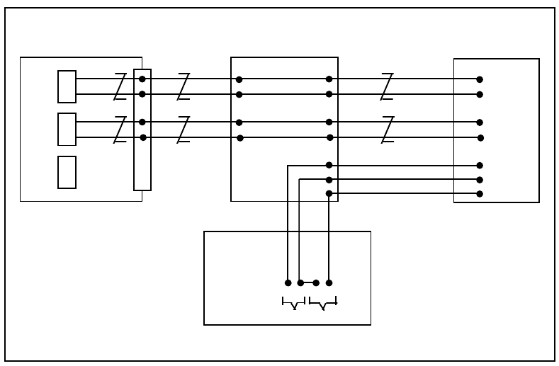
Figure 3-2: Interconnection diagram
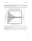
3.2 EMC Cabling and Earthing
To meet the EC Directive for EMC (Electromagnetic Compatibility), it is recommended that the meter be connected using
a suitable instrumentation cable and earthed through the meter body and pipework. The instrumentation cable should
have an individual screen, foil or braid over each twisted pair and an overall screen to cover all cores. Where permissible,
the screen should be connected to earth at both ends. Note that for intrinsic safety, termination of the screen to earth in
the hazardous area is NOT generally permitted.
Typical cables that are suitable are those that meet BS5308 Multi-pair Instrumentation Types 1 and 2, such as Belden
types 9500, 9873, 9874, 9773, 9774 etc.