


3098 Technical Manual Electrical Connections
3-1
Chapter 3
Electrical Connections
This chapter
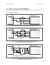
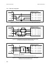
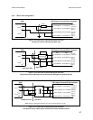
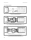
This chapter contains details and wiring diagrams for connecting the 3098 to 7950/51/55 Signal Converters and Flow
Computers, and more generally to other equipment in both hazardous and non-hazardous situations.
3.1 Introduction
The electrical connections to the 3098 are made to the 7812 gas density meter held inside the enclosure. When installed
in hazardous areas, connections between the meter and the power supply/readout equipment must be completed through
ZENER SAFETY BARRIERS [or galvanic isolators]. The electrical cable enters the enclosure (if supplied - see Important
Notice on page 1-1) through a cable gland assembly and then passes into the amplifier housing.
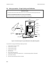
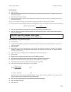
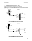
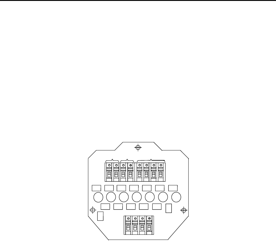
The meter terminal layout is shown in Figure 3-1.
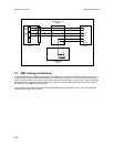
The amplifier housing has two chambers. The one nearest the cable gland axis contains the terminals for connection to
the meter/signal processing instrument. The other chamber contains the maintaining amplifier unit. The amplifier board is
encapsulated in a circular plastic container, with the complete module secured by a keyway and a centrally positioned
clamping screw. Behind the amplifier there is an interconnect terminal board which links the sensor to the maintaining
amplifier, and the amplifier to the user connect board (see Figure 3-2).
123
4567
8
9
1
10 11 12
SIG A
SIG B
PRT
Figure 3-1: Main Terminal Board Connections