


Maintenance & Fault Finding 3098 Technical Manual
5-4
5.2 Maintenance
Apart from scheduled calibration checks and filter replacements (these being dependent upon the condition of the sample
gas) no other routine maintenance should be required.
When a fault is suspected, the 3098 can be easily dismantled to expose the section that needs inspection. A full
dismantling procedure to major component level is described below.
1. Main meter (3098) removal: removal of the complete unit from its installation, allowing all other servicing to
be performed.
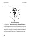
2. Density meter removal: removal of the sensing element to a clean environment where further dismantling can
take place.
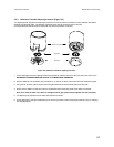
3. Reference Chamber Diaphragm removal: (performed after stage 1).
General Notes
• All gaskets, O-rings and the diaphragm are to be lightly greased with silicone grease MS4 before re-assembly.
Gas connection threads to be sealed using PTFE tape or Loctite 572.
• Loctite 221 is to be applied to all screws during re-assembly.
• New gaskets should be fitted on re-assembly.
• Any re-assembly must be followed by a leak test, procedure 5.2.7.
WARNING: BEFORE ANY SERVICING IS ATTEMPTED THE 3098 MUST
BE ISOLATED FROM BOTH THE GAS
AND ELECTRICAL SUPPLIES
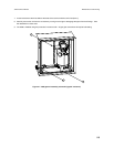
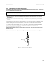
5.2.1 Main meter (3098) removal (Figure 5-1)
The instructions in this section apply only to 3098 meters supplied with an enclosure (see Important Notice on page 1-1). In
all other cases, please refer to the system installer.
1. Ensure that the 3098 has been isolated from the gas and electrical supplies. Vent the instrument to atmospheric
pressure.
Note: The reference chamber may remain charged with gas unless a reference chamber diaphragm requires servicing.
WARNING: FOR SOME GASES, E.G. METHANE, IT IS
IMPERATIVE TO VENT THE REFERENCE CHAMBER
TO ATMOSPHERIC PRESSURE WHENEVER THE 3098 HAS TO BE TAKEN OFF-LINE
2. Disconnect the 3098 externally from the system pipework at the side of the enclosure having vented the reference
chamber (if required). Cover all exposed gas connections.
3. The 3098 may be removed from its installation whilst still inside its enclosure, or it can be separated at this stage,
leaving the box in situ. If the latter is required then continue from 5.
4. The enclosure can now be removed from its installation by unscrewing the four mounting feet fixings.
5. Once the electrical wiring has been disconnected from the meter and the cable removed from the gland, the instrument
can be further dismantled. The 3098 metalwork can be removed from the enclosure as described in points 6 - 8 and
transported to a clean area for further servicing.
6. Remove the enclosure door by pulling out the two retaining pins. Undo the three Swagelok pipe fittings that connect
the gas lines to the unit at the enclosure wall (item a). When this is done, remove the two recess headed screws that
hold the unit’s mounting bracket to the rear of the enclosure (item b).