


3098 Technical Manual Electrical Connections
3-7
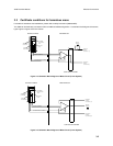
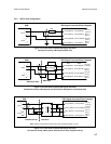
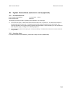
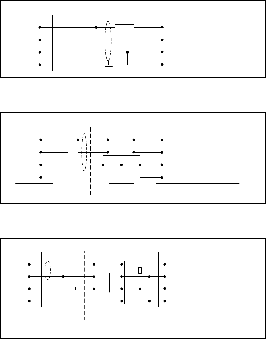
3.5.3 7951 2-wire configuration
3098 7951 Signal Converter/Flow Computer
1
+
SIG A
2
-
3
+
SIG B
4
-
330R
24V pwr +
PL5/9 (SK6/22)
Ch.1
PL5/1 (SK6/14)
PL5/2 (SK6/15)
PL5/10 (SK6/24)
PL5/9 (SK6/22)
Ch.2
PL5/3 (SK6/16)
PL5/4 (SK6/17)
PL5/10 (SK6/24)
Den ip +
Den ip -
24V pwr -
(0V dc)
(Den -)
(+24V dc)
(Den +)
Figure 3-5.15: 7951 Flow Computer/7951 Signal Converter
Gas Specific Gravity 2-Wire System (Safe Area)
3098 7951 Signal Converter/Flow Computer
1
+
SIG A
2
-
3
+
SIG B
4
-
MTL 787 (+ve)
3
4
1
2
Hazardous Area
Safe Area
24V pwr +
PL5/9 (SK6/22)
Ch.1
PL5/1 (SK6/14)
PL5/2 (SK6/15)
PL5/10 (SK6/24)
PL5/9 (SK6/22)
Ch.2
PL5/3 (SK6/16)
PL5/4 (SK6/17)
PL5/10 (SK6/24)
Den ip +
Den ip -
24V pwr -
(0V dc)
(Den -)
(+24V dc)
(Den +)
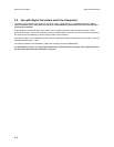
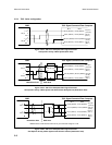
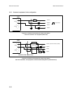
Figure 3-5.16: 7951 Flow Computer/7951 Signal Converter
Gas Specific Gravity 2-Wire System with Shunt-Diode Safety Barrier (Hazardous Area)
3098 7951 Signal Converter/Flow Computer
1
+
SIG A
2
-
3
+
SIG B
4
-
MTL 5032
4
5
14
13
Hazardous Area Safe Area
200R
1
12
11
2kR
24V pwr +
PL5/9 (SK6/22)
Ch.1
PL5/1 (SK6/14)
PL5/2 (SK6/15)
PL5/10 (SK6/24)
PL5/9 (SK6/22)
Ch.2
PL5/3 (SK6/16)
PL5/4 (SK6/17)
PL5/10 (SK6/24)
Den ip +
Den ip -
24V pwr -
(0V dc)
(Den -)
(+24V dc)
(Den +)
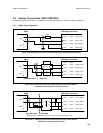
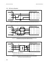
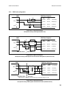
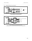
Note: Switches on MTL5032 should be set to give a threshold voltage of 3 volts
Figure 3-5.17: 7951 Flow Computer/7951 Signal Converter
Gas Specific Gravity 2-Wire System with Galvanic Isolator (Hazardous Area)