


3098 Technical Manual Electrical Connections
3-3
3.3 Certificate conditions for hazardous areas
For details of hazardous area installations, please refer to safety instructions (30985018/SI).
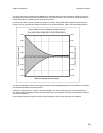
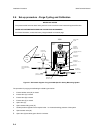
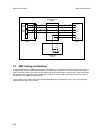
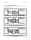
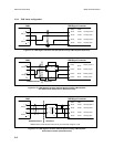
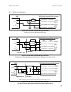
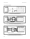
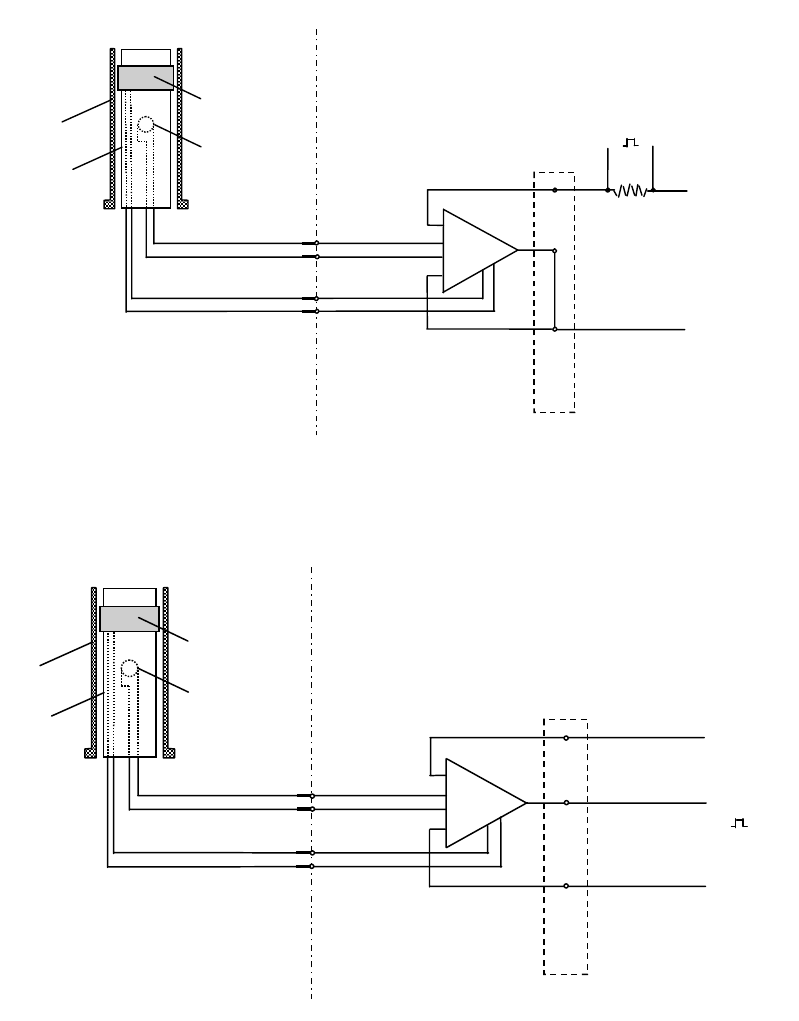
The 3098 can be electrically connected in either a 2-wire or 3-wire configuration. A schematic block diagram of these two
types is given in figures 3-3 and 3-4 below:
A
D
B
C
CYLINDER
ACTIVATING
COIL
PICK OFF
COIL
PART OF
SPOOLBODY
VIBRATING
CYLINDER
PICK OFF CURRENT
CYLINDER DRIVE CURRENT
USER CONNECT BOARD
NEGATIVE
SUPPLY
VOLTAGE (0V)
SIGNAL
OUTPUT
330R
POSITIVE
SUPPLY
VOLTAGE (+V)
SENSING ELEMENT AMPLIFIER UNIT
Figure 3-3: Schematic Block Diagram of Meter Circuit (2-wire System)
A
D
B
C
CYLINDER
ACTIVATING
COIL
PICK OFF
COIL
PART OF
SPOOLBODY
VIBRATING
CYLINDER
PICK OFF CURRENT
CYLINDER DRIVE CURRENT
USER CONNECT BOARD
NEGATIVE
SUPPLY
VOLTAGE (0V)
SIGNAL
OUTPUT
POSITIVE
SUPPLY
VOLTAGE (+V)
SENSING ELEMENT AMPLIFIER UNIT
Figure 3-4: Schematic Block Diagram of Meter Circuit (3-wire System)