


NOTES: The length of the exposed wires in the stripping process is critical. The
ideal length is 3/16 inches (5 mm). Any longer and the exposed wires may
touch, causing a short circuit between them. Any shorter and the wires
can be easily pulled out even if tightly fastened by the captive screws.
Do not tin the wires. Tinned wire does not hold its shape and can become
loose over time.
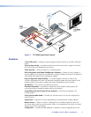
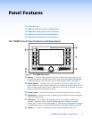
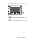
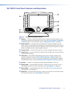
l Video Input — Connect an S-video or composite video source
to the unit, using these two BNC connectors:
For S-video, connect the Y (luminance) signal to the VID/Y
input and the C (chrominance) signal to the C input.
For composite video, connect the input to the VID/Y input.
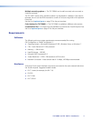
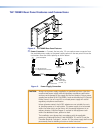
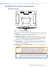
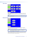
m Network Connector — The TLP 700MV connects to an Ethernet
LAN using a twisted pair cable, terminated with an RJ-45 connector
(see the figure at right). Use a straight-through Ethernet cable to
connect the panel to a switch or router. Use a crossover cable to
connect the panel directly to a computer.
Plug one end of the cable into the RJ-45 socket and the other
end into a network switch, hub, or router that is connected to an
Ethernet LAN or the Internet.
An Extron IP Link control interface must also be connected to the
same network domain. Suggested models are listed on page 3.
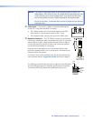
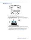
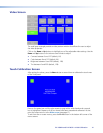
The LAN Port connector (see the figure at right) has two LED lights.
The Link LED lights green to indicate a good network connection.
The Activity LED blinks yellow when network activity occurs.
LAN
RJ-45
Port
Link
LED
Activity
LED
LAN Port
TLP 700MV and TLP 700TV • Panel Features 7