


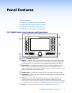
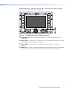
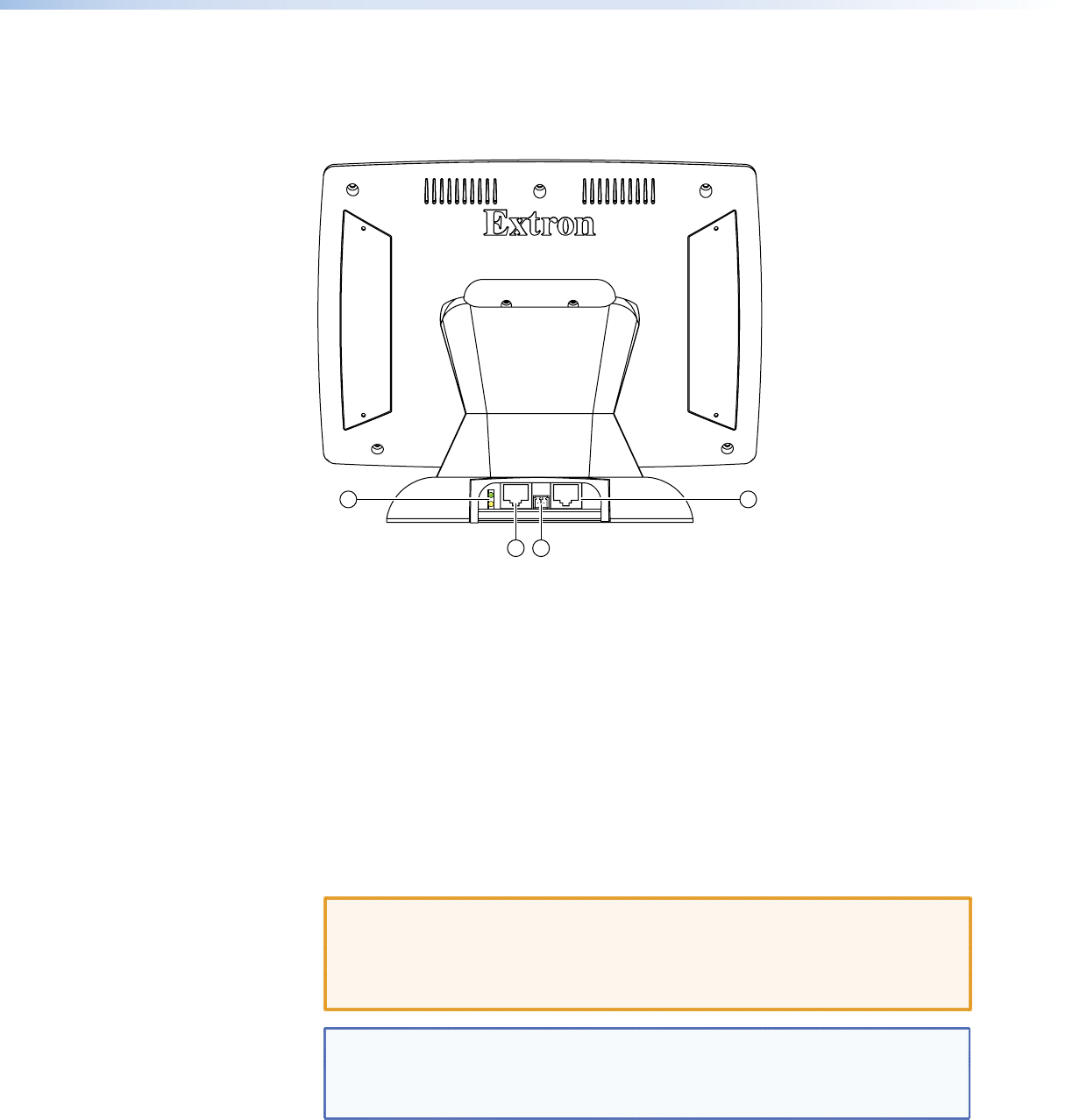
TLP 700TV Rear Panel Features and Connections
With Stand Attached
10 13
11 12
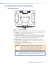
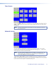
Figure 7. TLP 700TV Rear Features
The following connections are available through the back panel when the stand is in place:
j LED lights —The Link LED lights green to indicate a good network connection. The
Activity LED blinks yellow when network activity occurs.
k RJ 45 connector to LAN — Use straight-through twisted pair cable to connect the
TLP 700TV to a network switch or router. Use a crossover cable to connect the panel
directly to a PC. An Extron IP Link control interface must be connected to the same
network domain. A list of suggested models is given on page 3.
l Power connector — Connect the provided power supply to this 2-pole captive
screw connector. See the Caution on page 8 and the Notes on page 9 for important
information about the power supply.
m RJ 45 connector to Extron MTP Transmitter — Twisted pair input provides video
and audio input.
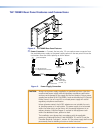
CAUTION: The left RJ-45 connector on the back of the TLP 700TV (with the
yellow and green LEDs) must be connect to a network. The right
RJ-45 connector must be connected to an Extron MTP Transmitter. The
MTP transmitter uses higher voltages than a LAN and inputting those
voltages on the network connection damages the TLP 700TV.
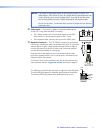
NOTE: Audio input is available only from an Extron MTP transmitter through the
RJ-45 connector in the base of the unit. If the base is removed from the
TLP 700TV, connections are via BNC connectors and there is no audio
input.
TLP 700MV and TLP 700TV • Panel Features 9