


0150-0193C 12 Calibur DVMR
e
Triplex
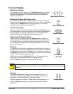
External Alarm Acknowledge Input
External Device: Normally Open
Zero potential relay contact.
Connect a switch or similar device to ground this pin in order
to acknowledge an alarm condition, and silence associated
buzzers and relays. Connect from pin 23 to either pin 18, 19,
or 20 (ground pins).
All specifications subject to change without notice. GE-Interlogix believes all specifications
to be correct at time of printing, but no liability is assumed for omissions or errors.
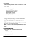
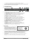
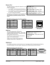
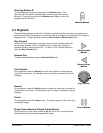
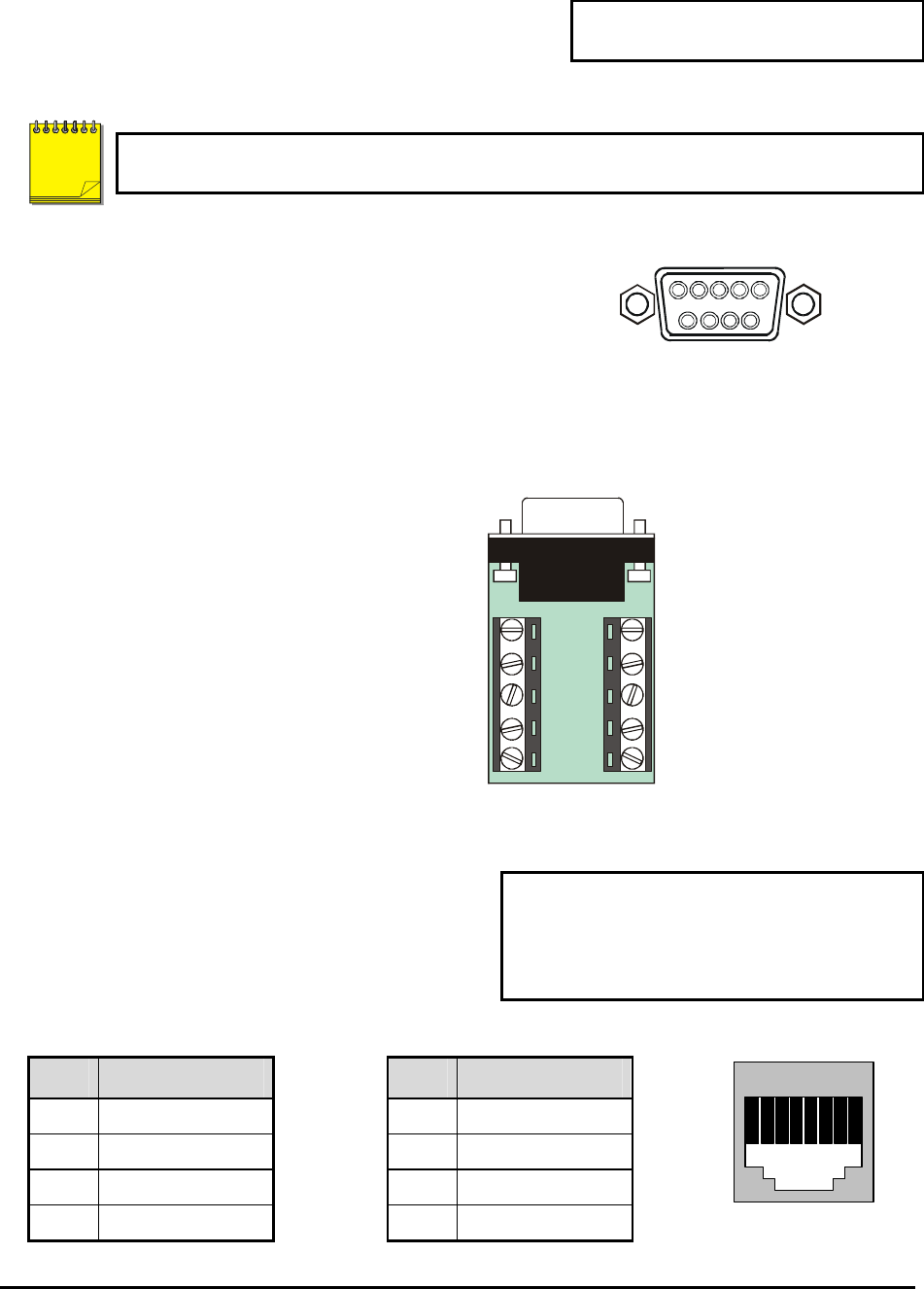
AUX Port
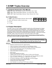
The back panel of the unit is equipped with an Aux Port
(DB-9 style connector).
Do not attempt to wire directly to the DB-9
connector on the back panel.
1
5
6
9
DB-9 Connector on Back Panel
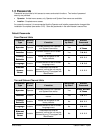
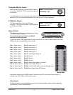
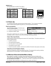
Connect the Accessory PCB (supplied with the audio equipped models) to the AUX port to access the
Audio features. Wire the audio input and output to the Accessory PCB per the pin out specifications
shown below.
Pin 1: Not Used.
Pin 2: Audio Out.
Pin 3: Ground.
Pin 4: Audio In.
Pin 5: Ground.
Pin 6: Not Used.
Pin 7: Ground.
Pin 8: Not Used.
Pin 9: Ground.
GND: Ground.
1
2
3
4
5
6
7
8
9
GND
Accessory PCB
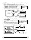
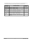
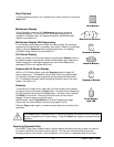
RS485 Connector
Wire Type:
#24 AWG, twisted pair with shield
(2-wire)
Connector Type: RJ-45
Max. Cable Length: 3200 feet / 1000 meters
Shields are grounded at one end, preferably at the
DVMR
e
Triplex.
See section 3.16 for information about configuring
the RS485 network address settings in the menu
system.
RJ-45 Pin Configuration For RS485 Port
Pin Use
Pin Use
1 Ground (Shield) 5 Not Connected
2 Not Connected 6 Network -VE
3 Network +VE 7 Ground (Shield)
4 Not Connected 8 Not Connected
82 3 4 5 6 71
RJ-45 socket on
back panel.
NOTE