


0150-0193C 9 Calibur DVMR
e
Triplex
• An external archive device, such as a DVSe, RAID, CD-R, DAT, or AIT drive.
For instructions regarding the connection of the associated security equipment in your system, please
consult the instruction manual of the associated equipment.
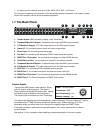
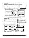
1.7 The Back Panel
B
B
SVHS
SCSI
RS-232/1
AUX
RS-485/1
10/100
ETHERNET
RS-485/2
RS-232/2
1 2 3 4 5 6 7 8 9 10 11 12 13 14 15 16
12V DC
1
2
3
4
5
6
7
8
9
10 11
12
13
14
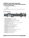
1. Camera Inputs: BNC connector, looping. Auto Terminating.
2. Composite Monitor-A Output: Composite video output with BNC style connector.
3. Y/C Monitor-A Output: Y/C video output with 4-pin mini-DIN style connector.
4. Alarm I/O: For connecting alarm inputs, and alarm output relays.
5. Power Input: For connecting the power supply.
6. Aux Port: For connecting the Accessory PCB for Audio inputs and outputs.
7. RS485 Port 1 Connector: For connecting to keyboard and other RS485 devices.
8. 10/100 Ethernet Port: For connecting to remote PC via ethernet network.
9. Composite Monitor-B Output: Composite video output with BNC style connector.
10. Y/C Monitor-B Output: Y/C video output with 4-pin mini-DIN style connector.
11. SCSI Port: For connecting SCSI compatible archive devices.
12. RS232 Port 1: For modem connection and external control of the unit.
13. RS485 Port 2 Connector: For connecting to keyboard and other RS485 devices.
14. RS232 Port 2: For Event Generation and ASCII Text insertion.
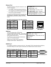
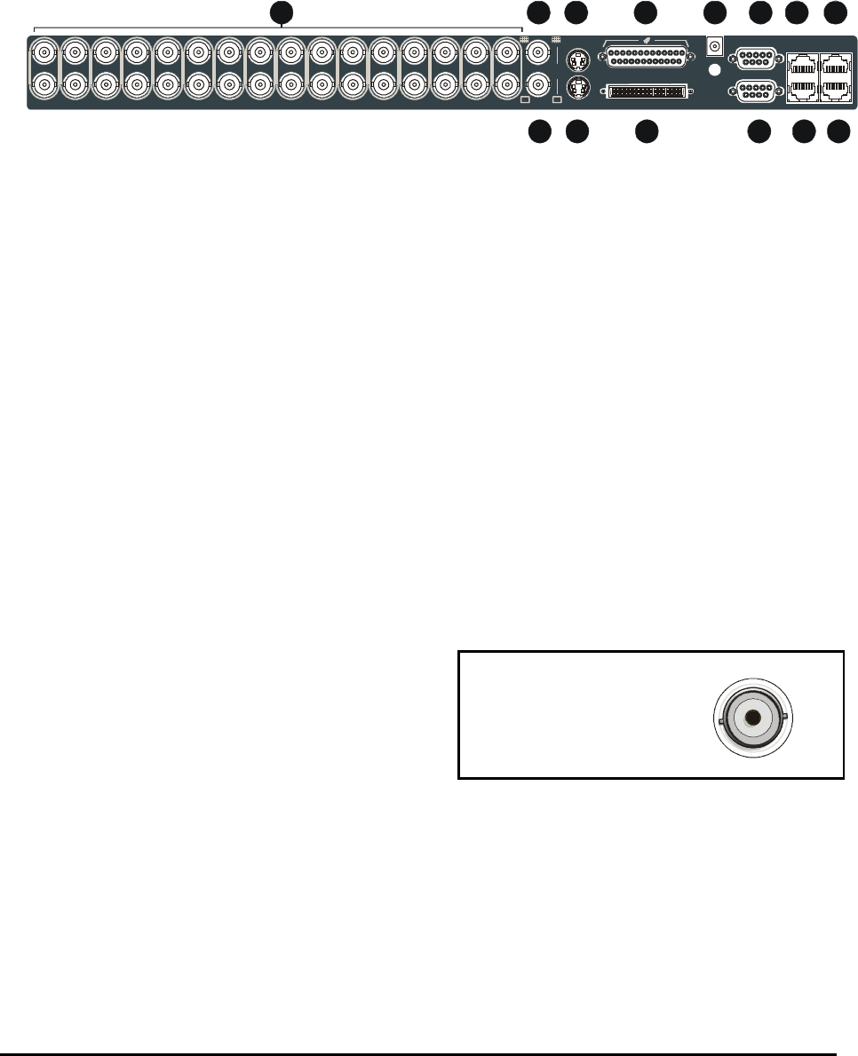
Camera Inputs
Cable: 75-Ohm Coaxial
Connectors: BNC
Auto Terminating: Yes
Passive Looping: Yes
There are two BNC jacks for each camera. Either
jack can receive a camera signal. The signal is
looped (directly connected to the other jack), making
the camera signal available to other equipment.
The camera input connectors are Auto Terminating.
This means that the input signal will automatically be terminated with 75-Ohms unless a 2
nd
cable is
connected to the 2
nd
BNC connector of the same camera input. Make sure there is 75-Ohm
termination at the end of the video line if the signal is looped through the DVMR
e
Triplex.
Time base correction is performed during digital capture. As a result, cameras do not require
synchronization.
See section 3.14 for information about disabling unused camera jacks in the menu system.