


Chapter 5
Troubleshooting
Possible Problems
113
Step 4. You have now reached the point where the failed Field Replaceable Unit (FRU or FRUs) have been
identified and need to be replaced. You must now perform the specific remove-and-replace
verification steps.
NOTE If multiple FRUs are identified as part of the solution, a fix cannot be guaranteed
unless all identified failed FRUs are replaced.
Step 5. There may be specific recovery procedures you need to perform to finish the repair. For example, if
the display panel is replaced, you need to restore customer-specific information.
Possible Problems
This section contains example HP server problems and their possible solutions.
The Server Does Not Power On
Step 1. Check to see if the iLO MP is working. If so, access the SEL to determine the problem.
Step 2. Check all power connection cables.
Step 3. Verify that 200-240 VAC power is available at the ac power receptacle. Check the receptacle output
with another device.
Step 4. Check the power supply fans to see if they are operating. The fans will operate off the dc voltage
generated by the power supply.
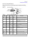
Step 5. Check that the Power LED on Front Control Panel is illuminated. See“Front Control Panel LED
Indicators” on page 117.
Step 6. Check all connections from the power supply to the power distribution module.
Step 7. Verify that all cables and modules are correctly connected. Especially check the display panel
connection.
Step 8. Review the installation procedures for the server. See the HP Integrity rx4640 Installation Guide.
Step 9. If the server starts to power-on and then power-off, a voltage rail of the power supply may be out of
specification. The BMC monitors voltages and prevents power-on when power values are out of
specification.
The Server Does Not Boot
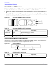
Step 1. Examine the front panel LEDs for warning or fault indications. The server LED will be flashing
yellow with a warning indication and flashing red with a fault indication. See “Front Control Panel
LED Indicators” on page 117.
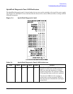
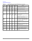
Step 2. Examine the QuickFind Diagnostic Panel for indications of specific warning or fault indications.
The diagnostic LEDs present patterns that categorize the source of the warning or fault. See
“QuickFind Diagnostic Panel LED Indicators” on page 119.