


Chapter 4
Removing and Replacing Components
Removing and Replacing the Midplane Riser Board
97
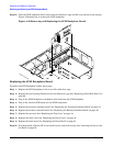
Replacing the Midplane Riser Board
To replace the midplane riser board, follow these steps:
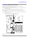
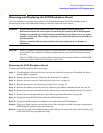
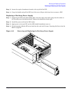
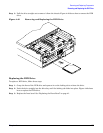
Step 1. Replace the midplane riser board onto the keyway slots on the chassis wall. Then push straight
down until it seats onto the locking studs. Figure 4-39 shows how to install the midplane riser
board.
Step 2. Using a torx #15 driver, replace and tighten the 5 torx screws attaching the midplane riser board to
the chassis.
Step 3. Plug in the QuickFind diagnostic board cable to the midplane riser board.
Step 4. Plug in the DVD relay board and front panel display board cable to the midplane riser board.
Step 5. Plug in the power distribution board power cable and signal cable to the midplane riser board.
Step 6. Replace the SCSI backplane board. See “Replacing the SCSI Backplane Board” on page 94.
Step 7. Replace the I/O baseboard assembly. See “Replacing the I/O Baseboard” on page 68.
Step 8. Replace the three chassis hot-swap fan units. See “Replacing a Hot-Swap Chassis Fan Unit” on
page 65.
Step 9. Replace the processor extender board. See “Replacing the Processor Extender Board” on page 54.
Step 10. Replace the memory extender board. See “Replacing the Memory Extender Board” on page 46.
Step 11. Replace the top cover. See “Replacing the Top Cover” on page 44.
Step 12. Replace the front cover. See “Replacing the Front Cover” on page 43.
Step 13. Replace the front bezel. See “Replacing the Front Bezel” on page 41.
Step 14. If rack mounted, slide the HP server back into the rack until it stops. See “Inserting the Server into
the Rack” on page 39.