Filename [DR-M10AG_AX_AA2_10Editing.fm]
Masterpage:Left+
80 EN
Page 80 May 7, 2004 2:42 pm
EDITING (cont.)
Output/Input Set
L-1 Output and L-1 Input Setting
(L-1 OUTPUT and L-1 INPUT)
The L-1 IN/OUT connector accepts and delivers either a
composite signal (regular video signal) or a Y/C signal (a signal
in which the luminance and chrominance signals are separated).
Set “L-1 OUTPUT” and “L-1 INPUT” to the appropriate mode
depending on the type of appliance connected to the unit’s L-1
IN/OUT connector.
NOTES:
● When you connect the unit using the provided cable adapter,
be sure to set “L-1 OUTPUT” to “SCART VIDEO”. If “L-1
OUTPUT” is set to “SCART S-VIDEO” or “SCART RGB”, the
image may be distorted.
● When using the provided output cable adapter, L-1 IN/OUT
connector can be used only as an output connector.
● Component video signals are not output from the L-1 IN/OUT
connector.
● When Progressive scan mode is engaged, it is not possible to
select the setting of “L-1 OUTPUT”. (
੬ pg. 99)
A
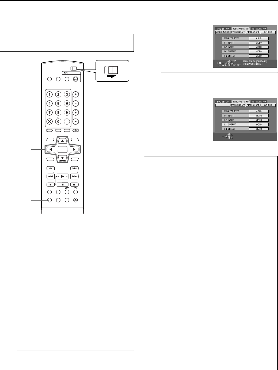
Access the Main Menu screen.
Press SET UP.
B
Access the Output/Input Set screen.
C
Select the output or input mode for the L-1
IN/OUT connector.
(The boldface settings in the table below indicate the settings at
your purchase.)
● Turn on the TV and select the AV mode.
● Slide the TV/DVD switch to DVD.
DVDTV
DVD
TIMER
PROG/CHECK
NEXTPREVIOUS
PAUSEREC
REC MODE LIVE CHECK
SET UP DISPLAY
ON SCREEN
OPEN/
CLOSE
SLOWSLOW PLAY/SELECT
STOP/
CLEAR
NAVIGATIONTOP MENU
RETURN
ENTER
MENU
STANDBY/ON
ABC
JKLGHI MNO
TUVPQRS WXYZ
AUXCANCEL
MEMO/MARK
DEF
CH
REC LINK
G-CODE
SHOW VIEW
TV
TV
MUTING
TV/
VIDEO
TV VOLUME
SET UP
rtwe
ENTER
DVDTV
A Press we to move the
arrow to“FUNCTION SET
UP”, then press ENTER.
B Press we to move the
arrow to “VIDEO IN/
OUT”, then press ENTER.
A Press rt to move the
arrow to “L-1 OUTPUT”
or “L-1 INPUT”, then
press ENTER.
B Press rt to select the
appropriate setting, then
press ENTER.
8 L-1 OUTPUT
SCART VIDEO: If a connected appliance’s input
is compatible only with regular
video signals, set to “SCART
VIDEO”.
SCART S-VIDEO*: If a connected appliance’s input
is compatible with Y/C signals,
set to “SCART S-VIDEO”. (For
connection, be sure to use a 21-
pin SCART cable that is
compatible with the Y/C signal.)
SCART RGB*: If a connected appliance’s input
is compatible with RGB signals,
set to “SCART RGB”.
COMPONENT: If a connected appliance’s input
is compatible with Y/P
B
/P
R
signals, set to “COMPONENT”.
You can obtain a high-quality Y/
P
B
/P
R
picture. Switch the TV to
the input that you can watch
component video pictures.
8 L-1 INPUT
VIDEO: If a connected appliance’s output
is compatible only with regular
video signals, set to “VIDEO”.
S-VIDEO*: If a connected appliance’s
output is compatible with Y/C
signals, set to “S-VIDEO”. (For
connection, be sure to use a 21-
pin SCART cable that is
compatible with the Y/C signal.)
* These settings are not correctly operative when using the
provided cable adapter.


