


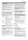
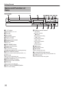
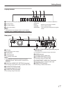
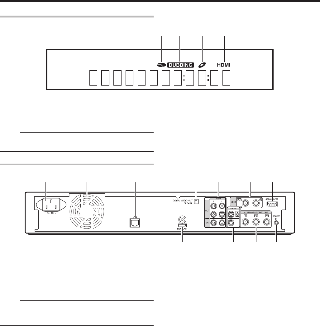
Display window
.
A B C D
A HDD/DISC remaining level display
B Dubbing display
C Disc status display
D HDMI output display
Memo:
v
The brightness of the display window can be adjusted.
For details, refer to “DIMMER (POWER ON)” (A page 83) .
English messages appear for a number of operations.
(Examples)
HELLO
:
When the power plug is inserted
READING
:
When reading the disc
ONSCREEN
:
Upon moving to the playback navigation
screen
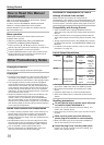
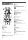
Rear panel
.
A B D F G
KJH
E
I
C
A AC inlet
For connecting the power supply.
B Cooling fan
C [LAN] terminal
For connecting a LAN cable.
Memo:
v
For SR-HD1350, this terminal functions as a [FOR
SERVICE] terminal. LAN connection is therefore not
supported.
D [DIGITAL AUDIO OUT (OPTICAL)] terminal
For connecting to the amplifier using an optical audio cable.
E [AUDIO OUT/IN] terminals
For connecting using an audio cable.
F [VIDEO OUT/IN] terminals
For connecting using a video cable.
G [SERIAL COM.(RS-232C)] terminal (only for
SR-HD1700)
For connecting to a computer using a serial cable.
H [HDMI] terminal
For connecting using an HDMI cable.
I [S-VIDEO OUT/IN] terminals
For connecting using an S-video cable.
J [COMPONENT VIDEO OUT] terminals
For connecting using a component video cable.
K [REMOTE IN] terminal
For connecting a wired remote control.
Getting Started
17