


17
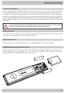
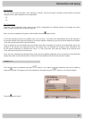
Separated:
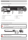
The second tuner input of the receiver, identied at the
rear of the unit by “LNB2 in”, receives its own signal input
(i.e. there is a direct connection between the antenna
socket and tuner input 2). See example illustration
on the right.
Before you start conguring the tuner for your type of reception system you must rst make both the “Tuner 2
connection type” and “Tuner 2 Signal Conguration” settings. Once you have made these settings, continue to follow
the directions for your type of reception.
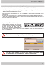
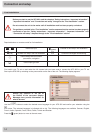
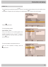
Tuner 2 Connection type
Select the type of connection for tuner 2 here. The currently selected setting is shown graphically in the connection
example at the top left of the screen. Either:
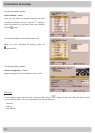
Different from Tuner 1:
The two tuners are connected to different signal sources
(separate cables from the LNB). See example illustration
on the right.
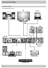
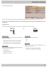
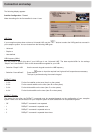
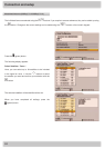
Tuner 2 Signal Conguration (only for “Separated” connection type)
Select the signal conguration for tuner 2 here. The currently selected setting is shown graphically in the connection
example at the top left of the screen. Either:
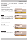
Loopthrough:
The second tuner input of the receiver, identied at
the rear of the unit by “LNB2 in”, receives the signal
currently looped through from the tuner 1 looped
through output, identied by “Loopthrough”. In this case,
the second tuner can only receive the channel level
currently being received by the rst tuner. See example
illustration on the right.
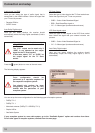
Same with Tuner 1:
Both tuners are connected to the same signal source.
See example illustration on the right.
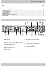
Connection and setup