


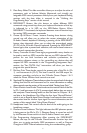

Rear Panel
1. Power Switch: The Power Switch turns on the M-Audio Ozone.You
probably figured that one out for yourself.
2. Power Jack:This jack is used to connect the keyboard to the supplied
9VAC 1000mA “wall-wart” type power supply.
3. USB Port: This USB connector jack is used to connect the M-Audio
Ozone to the computer’s USB port using a standard USB cable (included).
4. MIDI Out Jack, USB:This standard MIDI jack receives its source from the
computer when software’s set to M-Audio Ozone MIDI Out - & is used to
send MIDI messages to other MIDI instruments (such as a sound module).
5. MIDI Out Jack, Keyboard:This standard MIDI jack is a direct MIDI out
from the keyboard in “standalone” mode (independent of the
computer), and is used to send MIDI messages to another MIDI
instrument (such as sound module).
6. Sustain Jack:This jack allows you to connect an optional footswitch to
the keyboard. When the footswitch is depressed, MIDI controller
“pedal sustain” information is sent from the M-Audio Ozone, while
notes played on the keyboard will continuously sound as long as the
footswitch is held.
7. Headphone Out: This jack is a 1/4” TRS stereo headphone output
which plays the same signal as the main outputs. Headphone Out level
is controlled by the Headphone Level control.
8. Outputs 1 and 2: These are the main stereo audio outputs of the
M-Audio Ozone. This signal includes the stereo output from the
computer (via the USB cable), the Aux Input (when in Monitor mode),
and the Direct Monitor signals all mixed together.
9. Aux Input Monitor/Record switch:When this switch is set to Monitor,
the Aux Inputs are sent directly to the M-Audio Ozone’s Outputs 1 and
2, while Mic In (Channel 1) and Instrument In (Channel 2) are being
sent to the computer and also to the Direct Monitor circuitry.When
this switch is set to “Record,” the Mic In (Channel 1) and Instrument In
(Channel 2) are switched off (defeated), and the Aux Inputs are passed
to your computer and to the Direct Monitor circuitry.
10. Aux Input:This is a stereo 1/4” TRS jack for the two (L/R) Aux Inputs.
The Monitor/Record mode switch will determine its signal path.
11. Instrument In (Channel 2): This is a 1/4” TRS Balanced input for
instrument or line level signals. The Instrument In’s preamp gain is
controlled by the top panel “Inst Gain” control. This Channel is
defeated if the Aux Input is plugged in, and the Monitor/Record button
is pressed to the “Record” position.
7