


14
••••••••••••••••••••••••••••••••••••••••••••••••••••••••••••••••••••••••••••••••••••••••••••••••••••••••••••••••••••
Beginning
VIDEO
1
MAIN
OFF
ON
AC IN
~
234 56789
1
4
RESET
RS-232C
23 56789
1
ALARM IN
2
3
4
5
6
7
8
9
CLOCK ADJ
REC
EMERGENCY
MODE OUT 1
MODE OUT 2
MODE OUT 3
MODE OUT 4
MODE OUT 5
CALL OUT
CALL OUT GND
MAX 350mA
DC 12V OUT
GND
CAMERA OUT
RS-232C
RESET
CAMERA IN
INOUT
OUTPUT A
OUTPUT B
MIC
GND
AUDIO
100-240V
Y/C
ETHERNET
RECEIVE
SEND
12 13
11
109
876
5
1
23 4
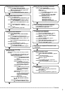
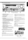
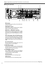
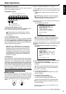
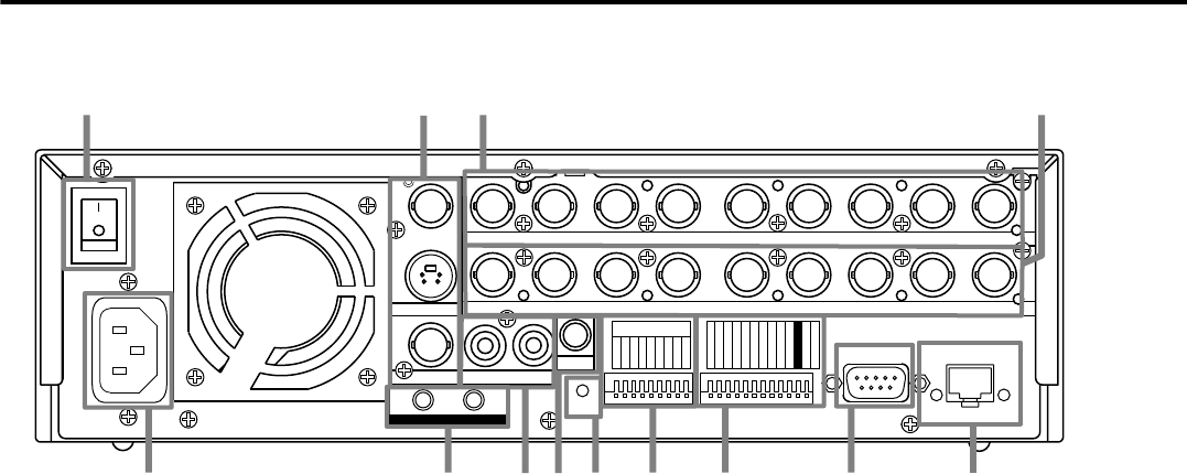
REC terminal
Input terminal to start recording. Not available dur-
ing timer recording.
EMERGENCY terminal
Input terminal initiating immediate shift to EMER-
GENCY recording mode compulsorily.
MODE OUT 1 ~ MODE OUT 5 terminals
Output terminal to indicate the unit’s current mode.
Select the unit’s condition by MODE OUT 1 ~ MODE
OUT 5 setting in the <REAR TERMINAL SETTINGS>
menu.
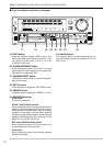
CALL OUT terminal / CALL OUT GND terminals
This is the ISOLATION output terminal. Information
that can be transmitted externally consists of CALL
OUT settings made on the <REAR TERMINAL SET-
TINGS> menu screen as well as fixed output set-
tings.
DC 12V OUT terminal
Will only output when the MAIN switch is ON. The
maximum electric current is 350mA.
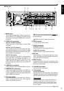
12. RS-232C connector
This connector is used to connect to host device with
RS-232C connector. This unit can be controlled by
another device through this connector.
13. ETHERNET connector
Use a 10BASE-T cable to connect to the Ethernet
terminal. Please use the cable adapted to 10BASE-
T. DUPLEX MODE is HALF DUPLEX.
RECEIVE indicator
Illuminates when the unit is receiving a signal.
SEND indicator
Illuminates when the unit is transmitting a signal.
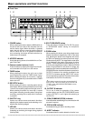
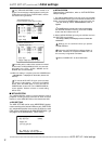
Major operations and their functions (continued)
■ Rear View (continued)