


38
••••••••••••••••••••••••••••••••••••••••••••••••••••••••••••••••••••••••••••••••••••••••••••••••••••••••••••••••••••••••••••••••••••••••••••
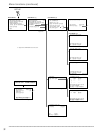
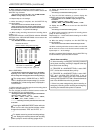
<MPX DISPLAY SETTINGS> (continued)
5. Turn the JOG dial to display the camera number to set and
turn the SHUTTLE ring clockwise.
• Flashing stops.
The same camera number can be set multiple
times on the split screen display. When multiple set-
tings with the same camera number have been
made, the playback image is displayed at the cam-
era location with the lowest number.
6. Repeat steps 4 and 5 to set the desired camera number.
7. When completed with setting, turn the SHUTTLE ring
counterclockwise.
• Setting is confirmed and the cursor appears.
9. Turn the SHUTTLE ring counterclockwise or press the SET
UP button.
The <SPLIT9 SCREEN SETTING> screen can-
not be exited when camera number is flashing.
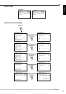
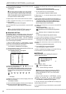
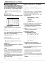
■ SEQUENCE SETTING
The display order of connected camera video can be
switched automatically or the switching time can be set.
Furthermore, the 3 types of split screen displays set in
“SPLIT4 SCREEN SETTING”, “SPLIT9 SCREEN
SETTING” can be switched automatically or the same cam-
era can be displayed repeatedly.
1. Press the SET UP button
}
<SETTINGS>
}
Select
“OUTPUT A” (“OUTPUT B) in the <MPX DISPLAY SETTINGS>
screen and turn the SHUTTLE ring clockwise.
• The <OUTPUT A> (<OUTPUT B>) screen appears.
2. Turn the JOG dial to select
}
“SEQUENCE SETTING” and
turn the SHUTTLE ring clockwise.
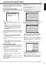
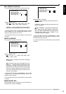
• The <SEQUENCE SETTING> screen appears.
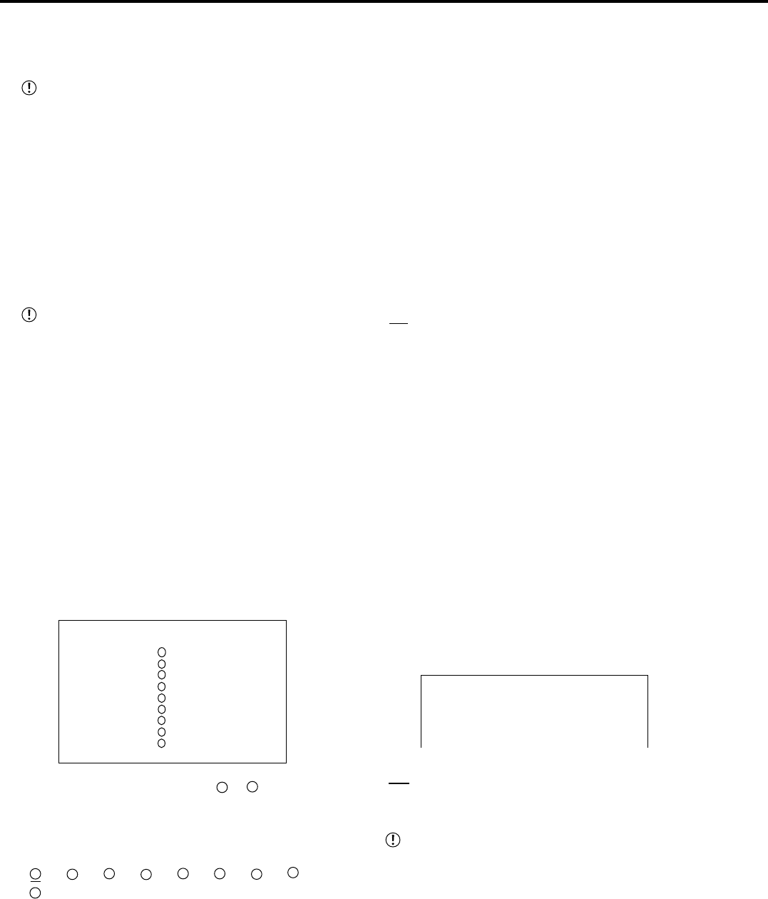
<SEQUENCE SETTING>
9
7
4
5
6
1
2
3
8
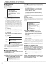
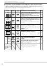
<SEQUENCE SETTING>
SEQUENCE NUMBER TIME
>>
1 2S
2 2S
3 2S
4 2S
5 2S
6 2S
7 2S
8 2S
9 2S
SPLIT4 abc 2S
3. Select the desired display order (
1
~
9
) and turn the
SHUTTLE ring clockwise twice.
• The camera number display reverses in color when the
SHUTTLE ring is turned the first time. When the ring is turned
for the second time, the background turns red and flashes.
• Setting
“
1
”, “
2
”, “
3
”, “
4
”, “
5
”, “
6
”, “
7
”, “
8
”,
“
9
”, “ - ”
“ - ” : No display.
4. Display the desired camera number to display and turn the
SHUTTLE ring clockwise.
• The setting is confirmed.
5. Turn the JOG dial clockwise to shift the reversed display to
“TIME” and turn the SHUTTLE ring clockwise.
• The background of the “TIME” setting turns red and flashes.
6. Display the desired time and turn the SHUTTLE ring
clockwise.
• The setting is confirmed and flashing stops.
• The time can be set at 1 second intervals (max. 30 seconds).
7. Turn the SHUTTLE ring counterclockwise.
• The cursor appears to sequence number on the left.
8. Repeat steps 3 ~ 7 to set other display orders of camera
number and time.
9. (When setting switching for SPLIT4 sequential display • • • )
Select “SPLIT4” and turn the SHUTTLE ring clockwise twice.
• The setting reverses in color when the SHUTTLE ring is
turned the first time. When the ring is turned for the second
time, the background turns red and flashes.
10. Display the desired item to set and turn the SHUTTLE
ring clockwise.
• The setting is confirmed.
• Setting of “SPLIT4” ( default : SPLIT4 “abc” )
“abc” : SPLIT4(a), (b) and (c) are displayed using sequence
display.
“ab” : SPLIT4(a) and (b) are displayed using sequence
display.
“a” : SPLIT4(a) is displayed using sequence display.
11. Turn the JOG dial clockwise to shift the reversed display
to “TIME” and turn the SHUTTLE ring clockwise.
• The background of the “TIME” setting turns red and flashes.
12. Display the desired time and turn the SHUTTLE ring
clockwise.
• The setting is confirmed and flashing stops.
13. Turn the SHUTTLE ring counterclockwise.
• The cursor appears to “SPLIT4” on the left.
14. When completed with all settings, turn the SHUTTLE ring
counterclockwise or press the SET UP button.
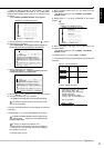
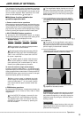
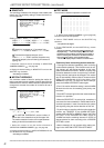
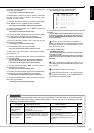
■ INTERLACE
The picture quality when splitting the screen of
camera video can be set.
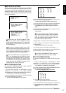
<OUTPUT A>
SPLIT4 SCREEN SETTING
SPLIT9 SCREEN SETTING
SEQUENCE SETTING
>>
INTERLACE ON
Setting ( default : “ON” )
“ON” : Video is displayed in detail.
“OFF” : Screen flickering is reduced.
Although screen flickering of video during SPLIT4
and SPLIT9 screen display can be reduced when
setting “INTERLACE” to “OFF”, the vertical resolu-
tion will drop.
1. Press the SET UP button
}
<SETTINGS>
}
Select
“OUTPUT A”(“OUTPUT B”) in the <MPX DISPLAY
SETTINGS> screen and turn the SHUTTLE ring clockwise.
• The <OUTPUT A> (<OUTPUT B>) screen appears.
2. Turn the JOG dial to select “INTERLACE” and display the
desired setting and confirm.
3. Turn the SHUTTLE ring counterclockwise or press the SET
UP button.